Timestamp-based all digital phase locked loop for clock synchronization over packet networks

a clock synchronization and packet network technology, applied in the field of network communication, can solve the problems of residual jitter up to the receiver clock signal, and achieve the effects of reducing jitter and noise in error signals, and being inexpensive to fabrica

Active Publication Date: 2010-02-02
CIENA
View PDF8 Cites 44 Cited by
  • Summary
  • Abstract
  • Description
  • Claims
  • Application Information

AI Technical Summary

Benefits of technology

[0006]In accordance with one embodiment of the invention, apparatus for synchronizing a local clock at a receiver with a clock at a transmitter, where indications of transmitter clock signals are communicated to the receiver as timestamps, comprises: a phase detector operable to compute an error signal indicative of differences between the timestamps and a local clock signal; a loop filter operable to reduce jitter and noise in the error signal, and thereby produce a control signal; a digital oscillator operable to oscillate at a frequency based at least in-part on the control signal, and thereby produce a digital oscillator output signal; and a timestamp counter operable to count pulses in the digital oscillator output signal, and output the local clock signal.
[0007]In accordance with another embodiment of the invention, a method for synchronizing a local clock at a receiver with a clock at a transmitter, where indications of transmitter clock signals are communicated to the receiver as timestamps, comprises the steps of: computing, with a phase detector, an error signal indicative of differences between the timestamps and a local clock signal; reducing jitter and noise in the error signal with a loop filter, thereby producing a control signal; producing a digital oscillator output signal with a digital oscillator operable to oscillate at a frequency based at least in-part on the control signal; and counting pulses in the digital oscillator output signal with a timestamp counter, thereby producing the local clock signal.
[0008]The all digital phase locked loop (“ADPLL”) offers advantages relative to currently known techniques. For example, the ADPLL alleviates some of the problems associated with its analog counterpart such as sensitivity to dc drifts and component saturations, difficulties encountered in building higher order loops, the need for initial calibration and periodic adjustments. Further, the ADPLL is relatively inexpensive to fabricate, is more reliable, smaller in size, and requires relatively few initial adjustments. Consequently, the ADPLL facilitates performance of elaborate real-time processing on digital samples.

Problems solved by technology

However, the presence of packet delay variation jitter and packet losses can affect the performance of the clock estimation / compensation process, making the transmitter clock appear faster or slower than it actually is, and ultimately, causing the propagation of some residual jitter up to the receiver clock signal.

Method used


Image

  • Timestamp-based all digital phase locked loop for clock synchronization over packet networks
  • Timestamp-based all digital phase locked loop for clock synchronization over packet networks
  • Timestamp-based all digital phase locked loop for clock synchronization over packet networks

Examples


Embodiment Construction

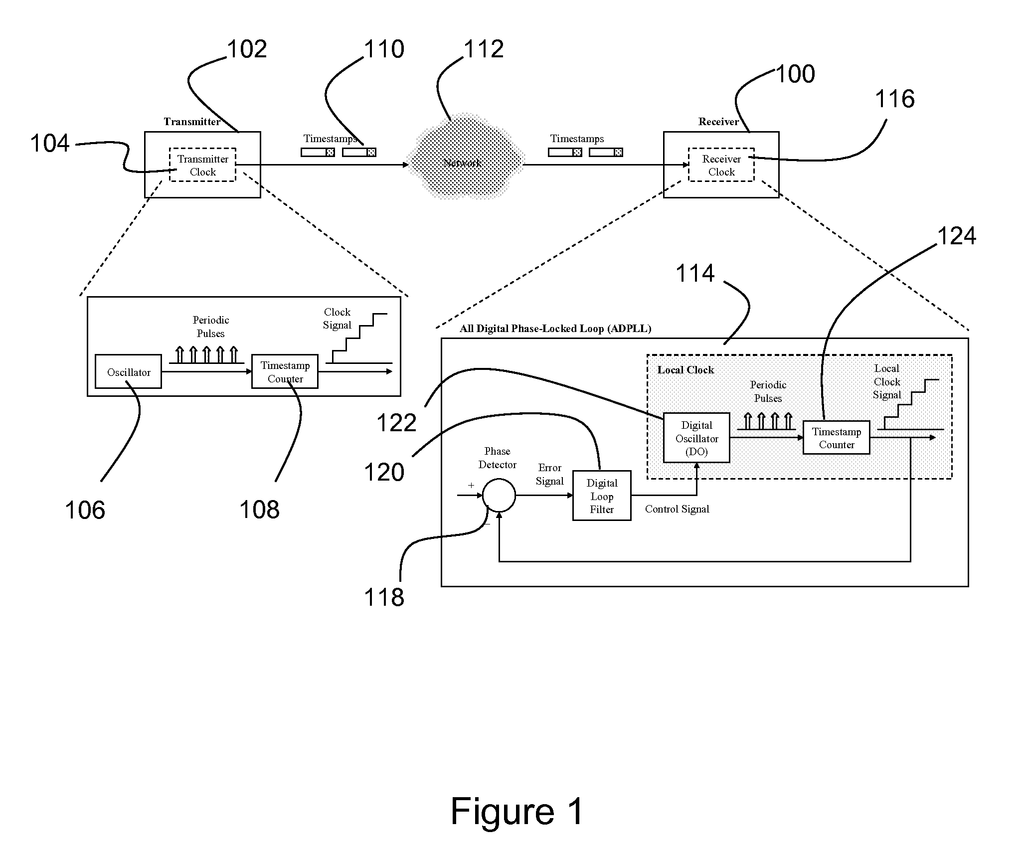
[0025]A block diagram of a clock synchronization technique based on timestamps is shown in FIG. 1. This technique enables multiple receivers (100) (only one receiver is illustrated) to synchronize their clocks to a transmitter (102). Examples of multiple receivers include broadcast and point-to-multipoint communications. The transmitter (102) includes a clock (104) having an oscillator (106) and a timestamp counter (108). The oscillator issues periodic pulses that are communicated to the timestamp counter. The timestamp counter is operable to count the pulses. The output of the timestamp counter represents the transmitter clock signal, and is incremented by a fixed amount at each pulse. Samples of transmitter clock signals are communicated to the receiver as timestamps (110) via a network (112).

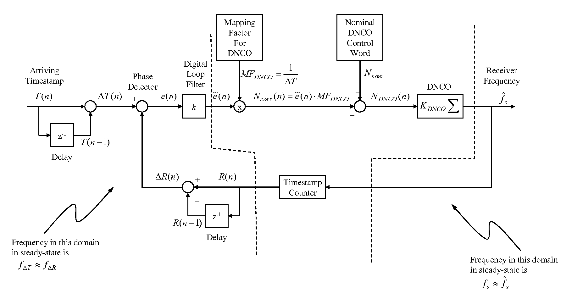
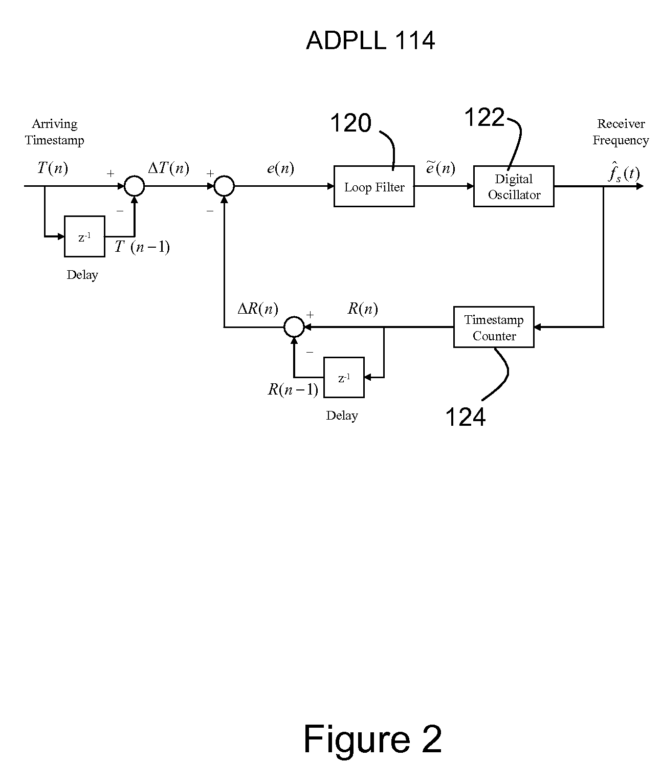
[0026]An all digital phase locked loop (“ADPLL”) (114) in a clock (116) at the receiver (100) uses the timestamps (110) as a reference signal to synchronize the receiver clock (116) with the ...


PUM


Abstract

A timestamp-based all digital phase locked loop is utilized for clock synchronization for Circuit Emulation Service (“CES”) over packet networks. The all digital phase locked loop at a CES receiver includes a phase detector, a loop filter, a digital oscillator and a timestamp counter. The all digital phase locked loop enables the CES receiver to synchronize a local clock at the receiver with a clock at a CES transmitter, where indications of transmitter clock signals are communicated to the receiver as timestamps. The phase detector is operable to compute an error signal indicative of differences between the timestamps and a local clock signal. The loop filter is operable to reduce jitter and noise in the error signal, and thereby produce a control signal. The digital oscillator is operable to oscillate at a frequency based at least in-part on the control signal, and thereby produce a digital oscillator output signal. The timestamp counter operable to count pulses in the digital oscillator output signal, and output the local clock signal.

Description

CROSS-REFERENCE TO RELATED APPLICATIONS[0001]This application is a Continuation-in-Part of U.S. patent application Ser. No. 10 / 076,415, entitled Technique for Synchronizing Clocks in a Network, filed Feb. 19, 2002 now U.S. Pat. No. 7,043,651, which is incorporated by reference. A claim of priority is also made to U.S. provisional patent application Ser. No. 60 / 732,276, entitled TECHNIQUE FOR DIFFERENTIAL CLOCK RECOVERY IN PACKET NETWORKS, filed Nov. 1, 2005, which is incorporated by reference.FIELD OF THE INVENTION[0002]This invention relates generally to the field of network communications, and more particularly to clock synchronization for Circuit Emulation Service.BACKGROUND OF THE INVENTION[0003]Circuit Emulation Service (“CES”) allows time division multiplexing (“TDM”) services such as DS-n and E-n circuits to be transparently extended across a packet network. With circuit emulation over IP, for example, TDM data received from an external device at the edge of an Internet Proto...

Claims


Application Information

Patent Timeline
IPC IPC(8): H03D3/24
CPCH03L7/093H03L7/0992H03L7/18H04J3/0632H04J3/0664
Inventor AWEYA, JAMESOUELLETTE, MICHELMONTUNO, DELFIN Y.FELSKE, KENT
Owner CIENA
Why Eureka
Try Eureka