
Detector

a detector and detector technology, applied in the field of detectors, can solve the problems of complex and expensive pressure vessels, inability to detect neutrons, and inability to achieve neutron detection,

Inactive Publication Date: 2009-12-22
UNIVERSITY OF HEIDELBERG
View PDF3 Cites 10 Cited by
  • Summary
  • Abstract
  • Description
  • Claims
  • Application Information

AI Technical Summary

Benefits of technology

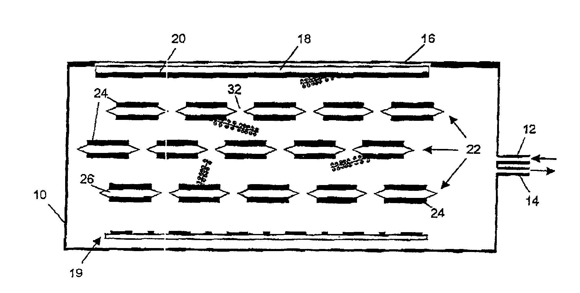
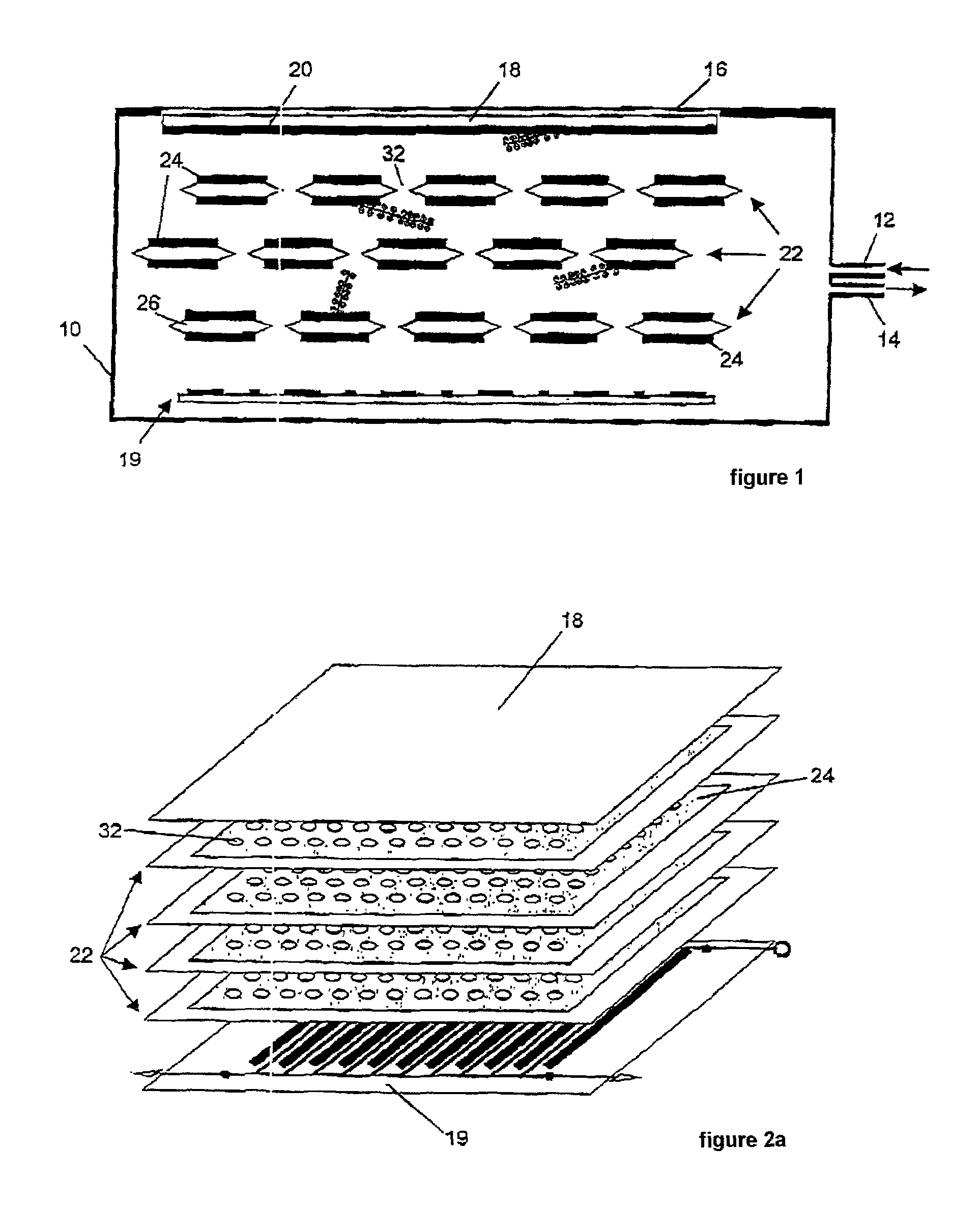
[0014]According to a particularly preferred embodiment, the detector has a multiplicity of, preferably 2 to 20, most preferably 10, converter devices arranged in cascade form (in series). In particular, the converter devices may in each case be arranged at a distance from one another in the form of a stack in the detector housing, so that the counting gas is situated between the converter devices. The result is a large active surface area for the interaction with the converter device which is required for detection of the neutral particles. Because of the charge-transparent nature of the converter devices, the charged particles which are generated by the conversion products and the detection of which allows the neutral particles to be detected can be moved through the cascade of converter devices to the readout device by means of the drift field. The use of converter devices arranged in cascade form in the detector according to the invention accordingly enables the interaction surface area available for the electrically neutral particles to be increased enormously and therefore enables the detection sensitivity to be increased considerably.
[0015]Preferably, a region of the converter device which is active in the conversion of the electrically neutral particles is of large-area, in particular planar, design and is preferably arranged substantially perpendicularly in the drift field. As well as planar surfaces, large-area structures which are curved as desired are also conceivable, for example cylindrical structures. This large-area or film-like structure of the converter device allows the surface to volume ratio of the converter device to be improved further. Although the (solid) converter material in the entire volume is typically sensitive to the neutral particles which are to be detected, the conversion products often only have a relatively restricted range in the converter material and therefore can only escape from this material if they lie sufficiently close to its surface; this means that to achieve a high detection sensitivity, it is advantageous, for a given converter volume and mass, to have as large a converter surface area as possible available for detection. Particularly efficient and rapid diversion of the charged electrical particles generated to the readout device is achieved if the converter device is arranged substantially perpendicularly in the drift field. Accordingly, the mean field direction of the drift field is advantageously substantially parallel to the surface normal of the converter device, which is of large-area design. An inclined arrangement of the converter device is also possible, provided that the plane of the large-area converter device does not run parallel to the drift field.
[0020]According to a further preferred embodiment, the first and second conductive layers of the converter device are electrically connected to one another via a device for generating a converter field. The device for generating a converter field makes it possible to generate an electrical drift field which in particular may act in addition to the drift field generated by the device for generating a drift field. This ensures that the electrically charged particles can be efficiently passed through the converter device.
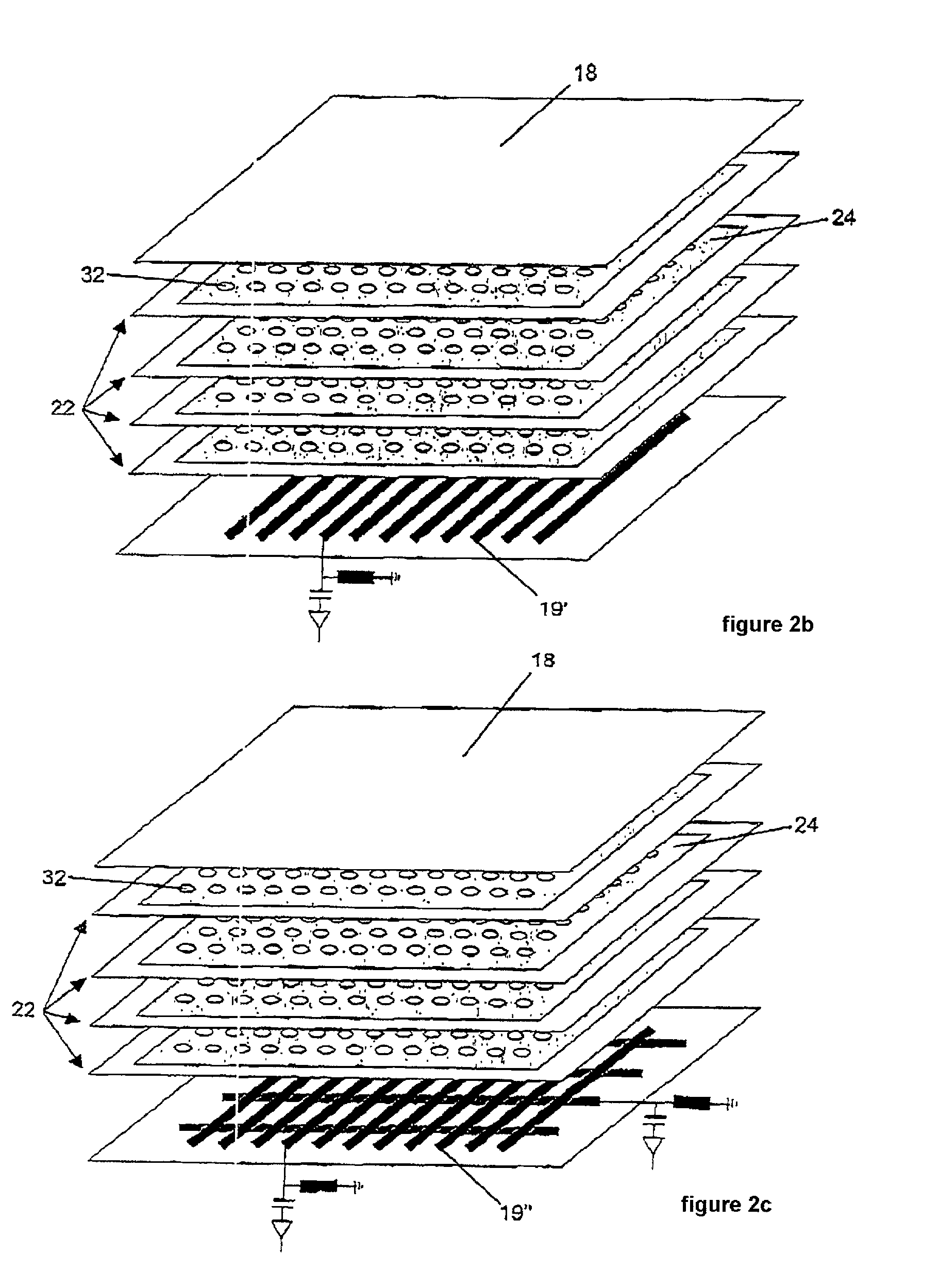
[0023]According to the invention, a converter device for a detector for detecting electrically neutral particles, in particular neutrons, comprises a first conductive layer and a second conductive layer which are electrically insulated from one another by an insulator layer arranged between them, and at least one (solid) converter layer, which is preferably arranged on the first conductive layer and / or on the second conductive layer, the converter device having a multiplicity of passages, which are preferably arranged in the form of a matrix, for electrically charged particles. A converter layer of this type can be used in combination with a conventional gas detector for simple and highly sensitive detection of neutral particles, in particular neutrons. For this purpose, the converter device is introduced into the drift field of the gas detector. It is particularly preferable if a “stack” of converter devices in a cascade arrangement is used rather than an individual converter device, since this allows the detection sensitivity to be increased enormously.
[0028]The charge-transparent design of the converter device enables the charged particles to be passed through the converter device(s) without losing their position information. It therefore follows from the charge transparency that the location where the charged particles are generated in the counting gas is reproduced or transferred without distortion through the converter device(s) to the readout device, which is preferably position-sensitive.

Problems solved by technology

For physical reasons, the detection of neutrons can only be achieved as a result of a nuclear reaction thereof with a neutron converter.
However, neutron detectors of this type in the form of conventional gas detectors with helium-3 as the neutron converter have considerable drawbacks.
The high operating pressure means that this requires complex and expensive pressure vessels.
On account of the design limitations of the pressure vessels, detection of neutrons above large detection areas can only be achieved with the aid of large detector arrangements which are in the form of a matrix and comprise a multiplicity of small individual detectors.
2 cm×10 cm and the typical counting rate acceptance of 10,000neutrons detected per second and cm2 of a neutron detector of this type are, however, highly unsatisfactory.
Vellettaz et al., “Two-dimensional gaseous microstrip detector for thermal neutrons”, Nuclear Instruments and Methods A 392 (1997), pages 73 to 79), the structure of these detectors is very complex and expensive even for a detector area of only 100 mm×100 mm, on account of the high gas pressure.
Furthermore, the MSGC technology has proven to be highly susceptible to faults.
A further drawback is the poor time resolution of the gas detectors which have been described to date.
However, detection of the scintillation light causes problems.
Since detection concepts of this type are relatively highly sensitive to X-radiation and gamma radiation, which cannot be avoided in a reactor or neutron environment, their possible applications are greatly restricted.
In particular, this background which is attributable to X-radiation and gamma radiation makes detectors of this type unsuitable for the individual detection of neutrons or the detection of very low neutron intensities, and consequently detector systems of this type are only able to detect distributions with intensive event rates in a positionally dependant manner.

Method used


Image

  • Detector
  • Detector
  • Detector

Examples


Embodiment Construction

[0038]FIG. 1 shows a highly diagrammatic sectional view and FIG. 2 shows diagrammatic perspective views of a detector for the detection of neutrons in accordance with one embodiment of the invention. The construction of the detector will be described first of all, with reference to FIGS. 1 and 2.

[0039]A gas (not shown) or counting gas is introduced into a detector housing 10, which may be part of a conventional gas detector, via a gas supply 12. There is also a gas outlet 14 for venting the detector housing. All counting gases which are customary for gas detectors can be used. All that is necessary is for the conversion products which are formed in the nuclear reaction which is to be described below to have an ionizing effect on the gas. Mixtures of argon with one or more of the components CO2 (10-90% share), CF4, dimethyl ether, isobutane and CH4 have proven particularly suitable. Unlike with conventional helium-3 neutron detectors, it is not necessary for the counting gas to be he...


PUM


Abstract

The invention relates to a detector for detecting electrically neutral particles. The detector has a housing (10) filled with a counting gas. A converter (22) in the housing (10) generates conversion products as a result of the absorption of the neutral particles. The conversion products generate electrically charged particles in the counting gas, and a readout device (19) detects the electrically charged particles. A device (18) generates an electrical drift field for the electrically charged particles in a region of the volume of the counting gas so that at least some of the electrically charged particles drift toward the readout device (19). The converter device (22) is of charge-transparent design and being arranged in the detector housing (10) so that the drift field passes through at least part of this device.

Description

BACKGROUND OF THE INVENTION[0001]1. Field of the Invention[0002]The invention relates to a detector for detecting electrically neutral particles, to a converter device for a detector for detecting electrically neutral particles, to a method for producing a converter device and to a detection method for detecting electrically neutral particles.[0003]2. Description of the Related Art[0004]The use of low-energy neutron radiation, known as thermal and cold neutrons, is an important method used in science (for example for applications in physics, chemistry, biology and medicine) and engineering (for example non-destructive testing). The basis for all the application areas in science and engineering is the detection of these neutrons, and consequently detectors and methods for detecting neutrons have become economically very important in recent decades. For physical reasons, the detection of neutrons can only be achieved as a result of a nuclear reaction thereof with a neutron converter. ...

Claims


Application Information

Patent Timeline
IPC IPC(8): G01T3/00H01J47/12
CPCH01J47/1211
Inventor KLEIN, MARTINSCHMIDT, CHRISTIAN
Owner UNIVERSITY OF HEIDELBERG
Learn More