
Diagnostic testing process and apparatus

a diagnostic test and apparatus technology, applied in the field of diagnostic testing process, can solve the problems of increasing the volume of sample, increasing the cost of sample, and reducing so as to improve the sensitivity of the assay and reduce the volume of sampl

Inactive Publication Date: 2007-04-17
PROTEOME SYST LTD
View PDF29 Cites 93 Cited by
  • Summary
  • Abstract
  • Description
  • Claims
  • Application Information

AI Technical Summary

Benefits of technology

"The present invention provides an apparatus and method for an assay process that improves sensitivity and reduces the volume of sample required for the assay. This is achieved by a pre-incubation step where the sample and detection analyte can bind together, which has two effects. Firstly, it allows for a higher sensitivity of the assay compared to lateral flow technology. Secondly, it reduces the amount of sample required for the assay. The apparatus includes a housing with a first member and a second member, and a chamber located between them. The sample and detection analyte can bind together in the chamber, which then flows through the membrane to the second member for reaction with the capture analyte. The pre-incubation step can be performed by placing the sample and detection analyte in the chamber and allowing them to incubate for a predetermined period of time. The sample can be a whole blood sample, and the pre-incubation step can be performed by removing the red blood cells and retaining the plasma in the chamber. The apparatus can be used for detecting reagents in whole blood or other body fluids."

Problems solved by technology

However, multiple disease diagnosis using lateral flow technology is very difficult because of differences in lateral diffusion between samples and variation in flow rates between batches of the partitioning membrane.
This means that antigen or antibody signal strengths may vary both within tests and between batches of tests, resulting in inconsistent results.
This advantage in speed however, is often at the expense of sensitivity.
A further disadvantage is that higher volumes of sample are required to achieve the same sensitivity as lateral flow.
This may be problematic in some situations.
The higher volumes of whole blood required for this would quickly block the membranes in the flow-through format.
It will be appreciated that the process described in U.S. Pat. No. 4,246,339, is a somewhat long drawn out, time consuming and tedious process and also lacks sensitivity.
Again the sensitivity of U.S. Pat. No. 5,185,127 is lacking and is not equivalent to that obtainable in lateral flow or ELISA formats.

Method used


Image

  • Diagnostic testing process and apparatus
  • Diagnostic testing process and apparatus
  • Diagnostic testing process and apparatus

Examples


example 1

[0080]Application of the Pre-filter Chamber

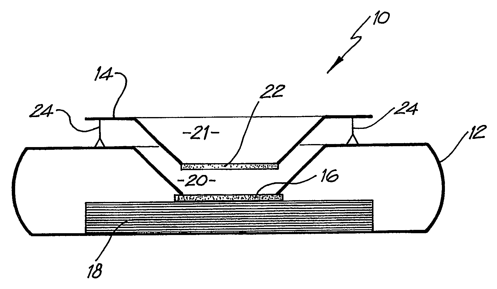
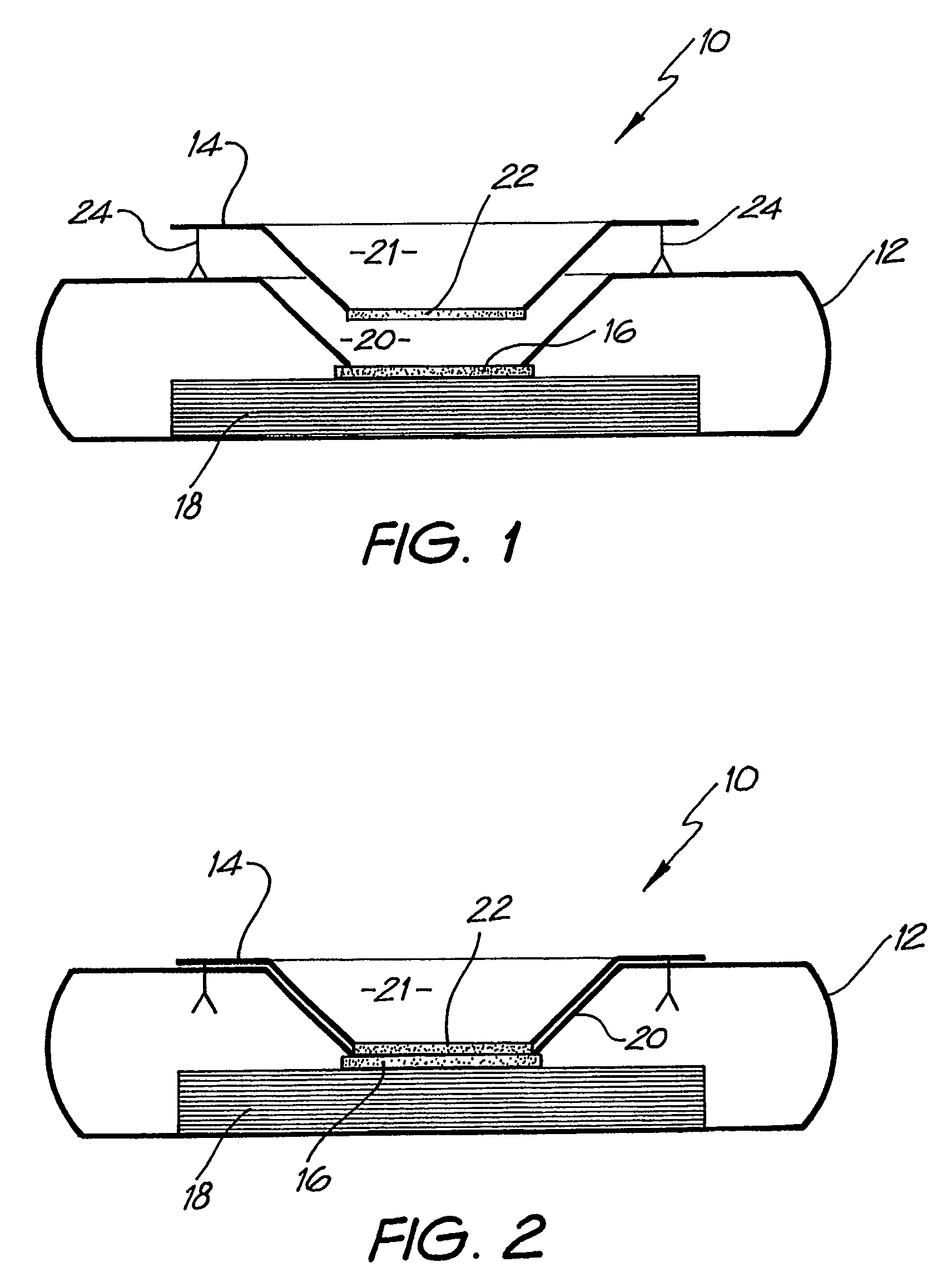
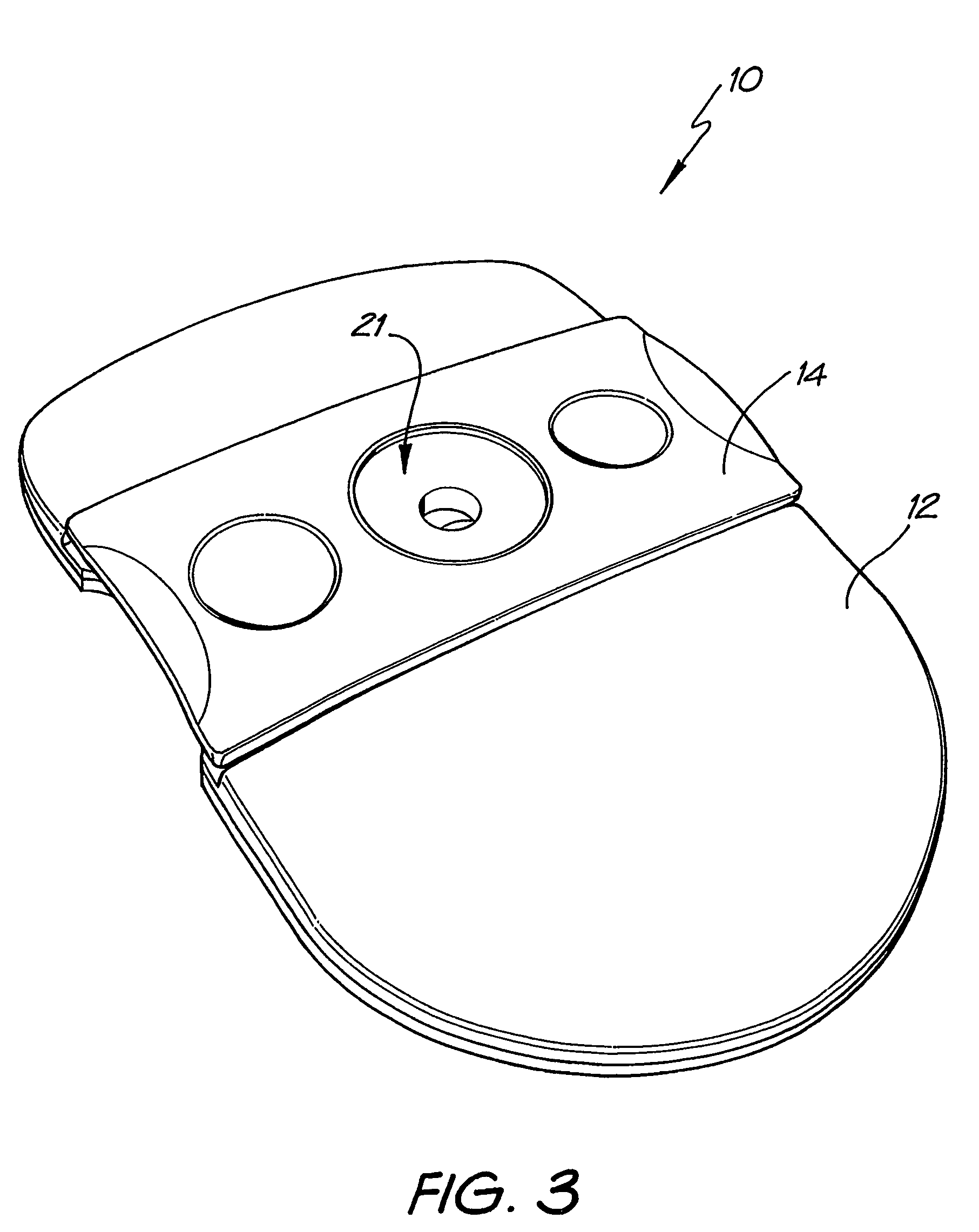
[0081]Whatman membrane (paper) or Reemay filters (polyester; 1 cm2) are inserted into the chamber 21 in the filter frame to form a conical retaining vessel (pre-filter unit).

[0082]The sample is pipetted into the plastic pre-filter chamber (50–100 ul) along with a detection analyte in the form of a detecting antibody (50–100 ul) bound to colloidal gold (particle size 20–50 nm). The sample is pre-incubated with the gold-conjugate (O.D.4) within the pre-incubation chamber for thirty seconds after gentle pippetting to ensure adequate mixing. After thirty seconds the chamber is pressed into the well 20 of the test cassette 12. Upon contact with the membrane 16 containing the detection zone, the solution filters through to the absorbent layer 18 beneath. The pre-filter 14 is discarded when the solution has filtered through and two drops of PBSA wash buffer are then added to the reaction membrane to wash away excess gold-conjugate revealing the re...

example 2

[0092]The assay device can also be used for detecting analytes in body fluids other than blood such as plasma, sera, urine, saliva and sputum. In this system, the sample can be retained in the pre-incubation chamber 22 by use of a hydrophobic membrane such as Reemay or Hollingsworth and Vose 7303 instead of the Whatman grade 1 membrane or a 0.22 μm hydrophilic Durapore membrane filter described above. The sample is mixed with the detection analyte for the required pre-incubation period. To obtain efficient flow through capillary action to the absorbent layer 18 when the pre-incubation chamber 22 is lowered onto the cassette 12, one of two procedures can be followed:

[0093]1. The membrane 16 containing the capture analyte is pre-wet with at least one drop of wash buffer containing 0.01 M phosphate, 0.15 M NaCl, 0.0% Azide, 0.5% Tween 20 or any wetting agent containing a detergent;

[0094]2. The membrane 16 containing the capture analyte is blocked with a hygroscopic solution such as suc...


PUM

PropertyMeasurementUnit
diameteraaaaaaaaaa
diametersaaaaaaaaaa
volumesaaaaaaaaaa

Abstract

A method and apparatus for use in a flow through assay process is disclosed. The method is characterised by a “pre-incubation step” in which the sample which is to be analysed, (typically for the presence of a particular protein), and a detection analyte (typically an antibody bound to colloidal gold or a fluorescent tag) which is known to bind to the particular protein may bind together for a desired period of time. This pre incubation step occurs before the mixture of sample and detection analyte come into contact with a capture analyte bound to a membrane. The provision of the pre-incubation step has the effect of both improving the sensitivity of the assay and reducing the volume of sample required for an assay. An apparatus for carrying out the method is disclosed defining a pre-incubation chamber for receiving the sample and detection analyte having a base defined by a membrane and a second membrane to which a capture analyte is bound. In one version the pre-incubation chamber is supported above the second membrane in one position but can be pushed into contact with the membrane carrying the capture analyte thus permitting fluid transfer from the incubation chamber through the capture membrane. In another version the membrane at the base of the incubation chamber is hydrophobic and its underside contacts the capture membrane and when a wetting agent is applied to the contents of the pre-incubation chamber fluid transfer occurs.

Description

RELATED APPLICATIONS[0001]This application is the U.S. National Phase of International Application No. PCT / AU02 / 01119, filed 20 Aug. 2002, published in English, which application claims priority under 35 U.S.C. § 119 or 365 to Australian Application No. PR 7144, filed 20 Aug. 2001, Australian Application No. PR 9451, filed 12 Dec. 2001, and Australian Application No. 2002950212, filed 11 Jul. 2002. The entire teachings of the above applications are incorporated herein by reference.FIELD OF THE INVENTION[0002]This invention relates to a diagnostic testing process and in particular to an apparatus for use in carrying out an assay process and to a method of carrying out an assay process using that apparatus.BACKGROUND OF THE INVENTION[0003]Lateral flow and flow-through technology have been used for diagnostic assays for almost twenty years. Lateral flow technology is currently dominant because lateral flow devices are easy to produce and the assay can be performed in a simple 2-step pr...

Claims


Application Information

Patent Timeline
Patent Type & Authority Patents(United States)
IPC IPC(8): G01N33/543B01L3/00
CPCB01L3/5023G01N33/54306G01N33/54366B01L2200/0642B01L2300/0825B01L2300/16B01L2400/0406B01L2400/0633Y10S435/81Y10S435/973Y10S436/81Y02A50/30
Inventor COLE, ROBERT ALANSLOANE, ANDREW JOHNHUNTER, WILLIAM SAMUEL
Owner PROTEOME SYST LTD
Learn More