
Sound-absorbing panel and production method of the same

a technology of sound-absorbing panels and production methods, which is applied in the direction of walls, flooring, instruments, etc., can solve the problems of not being able to obtain a sound-absorbing plate, the relationship between the percentage of void space and the maximum sound-absorbing coefficient is not uniform or constant, and it is not always possible to achieve a sound-absorbing plate. , to achieve the effect of easy replacement or replacement of only porous veneers, easy design changes, and increased sound-absorbing panels

Inactive Publication Date: 2009-10-13
YAMAHA CORP
View PDF13 Cites 12 Cited by
  • Summary
  • Abstract
  • Description
  • Claims
  • Application Information

AI Technical Summary

Benefits of technology

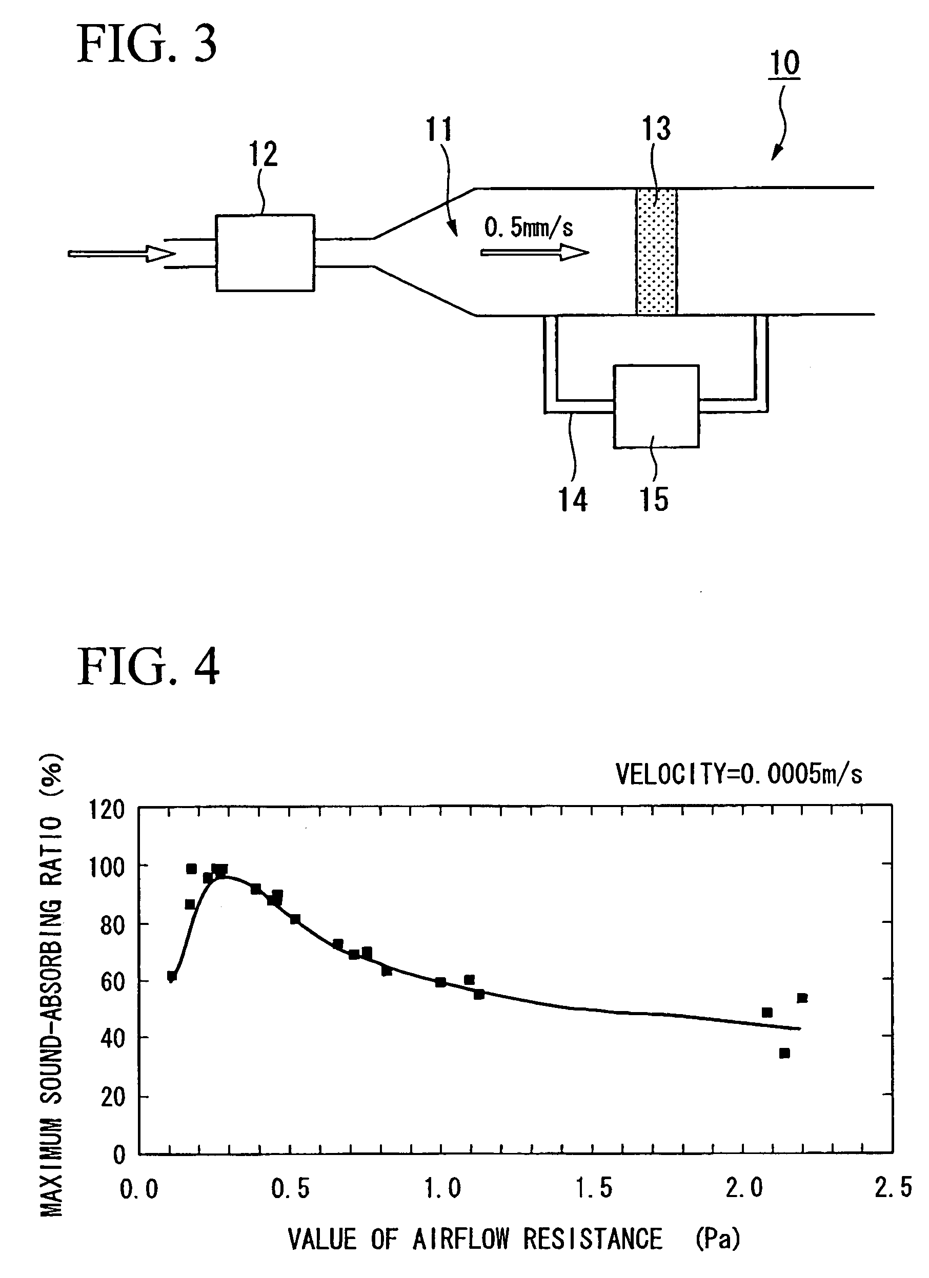
The present invention relates to a sound-absorbing panel with excellent sound-absorbing characteristics. The invention is based on the discovery that there is a close relationship between the value of airflow resistance and the maximum sound-absorbing coefficient. The invention provides a panel with a specific range of airflow resistance to achieve the maximum sound-absorbing coefficient. The panel includes a porous veneer with pierced apertures and a porous sound-absorbing base material arranged at the backside of the porous veneer. The value of airflow resistance is set to be in the range of 0.1-1.0 Pa. The invention also provides a method for producing the sound-absorbing panel with stable sound-absorbing characteristics. The invention solves the problem of inconsistent maximum sound-absorbing coefficients among different products. The invention also allows for easy replacement of the porous veneer and the supporting base material, and provides a design freedom for the appearance of the sound-absorbing panel. The invention further provides a sound-absorbing panel with excellent sound-absorbing characteristics.

Problems solved by technology

Therefore, there is a problem in which the appearance of this sound-absorbing plate is determined in accordance with the size of the open aperture and the appearance of the metallic porous sound-absorbing material, and there is a small freedom of design.
Therefore, there is a problem in which the appearance of the metallic plate is mainly determined in accordance with the radius and intervals of the pierced apertures, and there is a small freedom of design.
Moreover, the sound-absorbing veneer disclosed in Japanese Patent No. 2993370 has limitations to the material of the veneer because a pulse laser processing machine is used upon forming fine or small apertures on the veneer; therefore, there is a problem in which the freedom of designing is small.
However, inside the fiber sound-absorbing material and the granular sound-absorbing material, vacant spaces are generated in different ways; therefore, a relationship between the percentage of void space and the maximum sound-absorbing coefficient is not uniform or constant.
It is not necessarily possible to obtain a sound-absorbing plate which has an excellent maximum sound-absorbing coefficient even if the percentage of void space is applied as the indicator and the porous sound-absorbing material is selected.
In other words, even if the percentage of void space is the same, there is a difference in pass or channel in which air flows in accordance with the constitutional members; therefore, a relationship between the percentage of void space and the sound-absorbing coefficient is not uniform or constant.

Method used

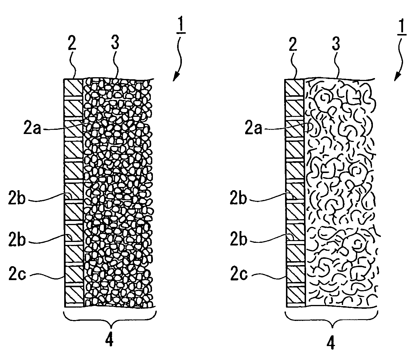
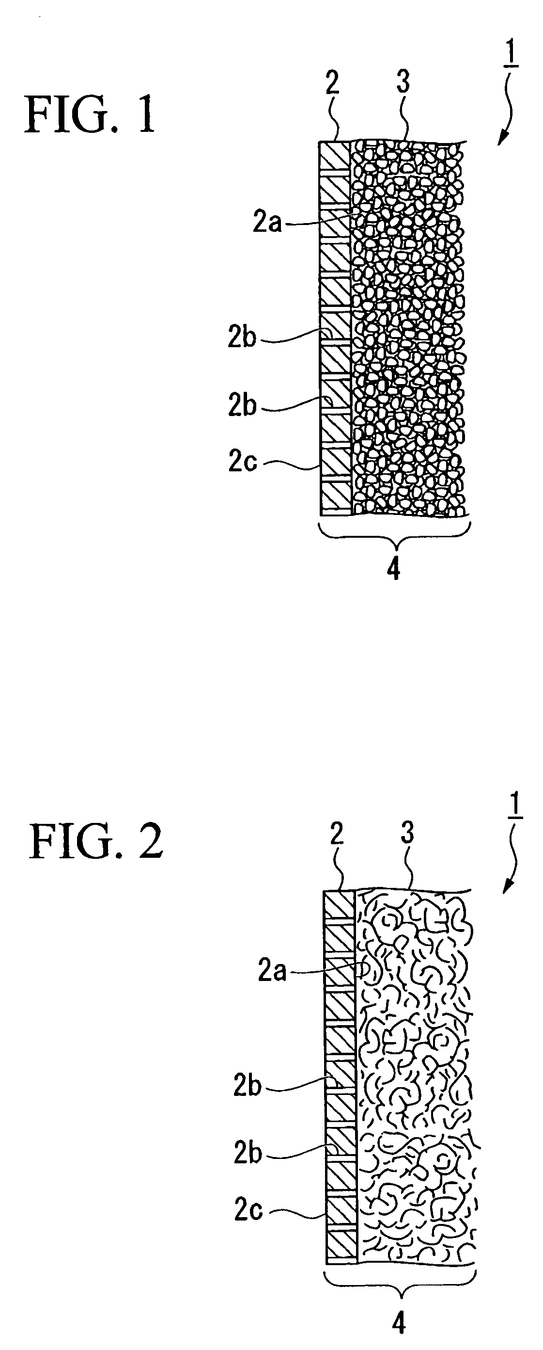

Image

  • Sound-absorbing panel and production method of the same
  • Sound-absorbing panel and production method of the same
  • Sound-absorbing panel and production method of the same

Examples


example 1

[0081]A porous veneer which has 30.9% aperture ratio is produced by forming pierced apertures of 70 μm diameter (0.07 mm) with 0.12 mm intervals between them by applying sandblast on a veneer which is a stainless veneer of 50 μm (0.05 mm) thickness prepared beforehand and on which design is processed beforehand.

[0082]Next, as the porous sound-absorbing base material, a glass wool of 50 mm thickness (product name: glass wool 32K, produced by ASAHI FIBER GLASS Co., Ltd) was prepared and the panel main body was formed by adhering this porous sound-absorbing base material to the porous veneer. The value of the airflow resistance of the panel main body was 0.3 Pa. The sound-absorbing panel of the example 1 is produced in such manner.

[0083]With respect to the sound-absorbing panel of the example 1, normal incidence sound-absorbing characteristics are measured in the case of setting the thickness of the backside air layer to be 0 mm. FIG. 7 shows the results. FIG. 7 shows normal incidence ...

example 2

[0085]The porous veneer was produced in the same manner as the example 1 except for processing an etching on the veneer.

[0086]Next, as the porous sound-absorbing base material, an aluminum sheet of 1 mm thickness (product name: Altone, produced by NICHIAS Corporation) was prepared and the panel main body was formed by adhering this porous sound-absorbing base material to the porous veneer. The value of the airflow resistance of the panel main body was 0.2 Pa. The sound-absorbing panel of the example 2 is produced in such a manner.

[0087]With respect to the sound-absorbing panel of the example 2, normal incidence sound-absorbing characteristics are measured in the case of setting the thickness of the backside air layer to be 150 mm. FIG. 8 shows the results. FIG. 8 shows normal incidence sound-absorbing characteristics measured in the case of applying only the porous sound-absorbing base material of 1 mm thickness (product name: Altone, produced by NICHIAS Corporation) as well.

[0088]A...

example 3

[0089]A porous veneer which has 30.9% aperture ratio is produced by forming pierced apertures of 70 μm diameter (0.07 mm) with 0.12 mm intervals between them by applying EB (Electron Beam) processing on a veneer which is a stainless veneer of 50 μm (0.05 mm) thickness prepared beforehand and on which a design is processed beforehand.

[0090]Next, as the porous sound-absorbing base material, an aluminum sheet of 1 mm thickness (product name: Altone, produced by NICHIAS Corporation) was prepared and the panel main body was formed by adhering this porous sound-absorbing base material to the porous veneer. The value of the airflow resistance of the panel main body was 0.2 Pa. The sound-absorbing panel of the example 3 is produced in such manner.

[0091]With respect to the sound-absorbing panel of the example 3, normal incidence sound-absorbing characteristics are measured in the case of setting the thickness of the backside air layer to be 150 mm. FIG; 9 shows the results. FIG. 9 shows norm...


PUM

PropertyMeasurementUnit
aperture diametersaaaaaaaaaa
radiusaaaaaaaaaa
radiusaaaaaaaaaa

Abstract

In order to provide a sound-absorbing panel and a production method of the same which has excellent freedom of design and have small differences in the maximum sound-absorbing coefficients among products, a sound-absorbing panel is adopted which is characterized by a panel main body which is constituted by arranging both a porous veneer of 0.02-0.5 mm thickness with multiple pierced apertures of 0.1 mm or smaller aperture diameters or 0.2 mm or smaller aperture diameters and a porous sound-absorbing base material set at a backside of the porous veneer so as to be overlapped, and is characterized by having a value of airflow resistance in a range of 0.1-1.0 Pa.

Description

BACKGROUND OF THE INVENTION[0001]1. Field of the Invention[0002]The present invention relates to a sound-absorbing panel and a production method of the same.[0003]Priority is claimed on Japanese Patent Application No. 2006-097002, filed Mar. 31, 2006, and Japanese Patent Application No. 2007-001186, filed Jan. 9, 2007, the contents of which are incorporated herein by reference.[0004]2. Description of Related Art[0005]Conventionally, a sound-absorbing panel constituted from a porous plate, a sound-absorbing panel which has a constitution of combination of both the porous plate and a porous sound-absorbing material are generally known. Japanese Patent Application No. H06-348281 discloses a sound absorbing panel which is constituted by providing multiple open aperture portions on a plate member, and by pressing, adhering and integrating the open aperture portions with a metallic porous sound-absorbing material of the same shape as these open aperture portions.[0006]Moreover, Japanese P...

Claims


Application Information

Patent Timeline
Patent Type & Authority Patents(United States)
IPC IPC(8): E04B1/82E04B2/02E04B2/14E04B1/62E04B1/74
CPCE04B1/86G10K11/162E04B2001/8476E04B2001/8461
Inventor NAKAMURA, YASUTAKA
Owner YAMAHA CORP
Learn More