High pulse-energy, eye-safe lidar system

Active Publication Date: 2009-09-01
UNIV FOR ATMOSPHERIC RES
View PDF11 Cites 157 Cited by
  • Summary
  • Abstract
  • Description
  • Claims
  • Application Information

AI Technical Summary

Benefits of technology

[0007]The present invention relates to a lidar system and system components for enabling long range and / or high temporal resolution atmospheric analyses. In particular, the invention includes a transmitter that enables transmission of high pulse energy, eye-safe beams with minimal divergence. Additionally, a high optical efficiency, high range resolution receiver is provided. The invention also enables lidar system applications requiring a long range, high spatial and temporal resolution lidar system such as scanning and volume imaging applications.
[0008]It has been recognized that system optimization for various lidar applications depends on achieving improved temporal resolution. That is, sufficient backscatter energy to support the desired analysis, e.g., imaging or particle characterization, needs to be obtained within a reasonably short time window. For example, in order to image a substantial volume of the atmosphere with a desired resolution by obtaining multiple images, and to accomplish such volume imaging within a time period where structures to be imaged are not dramatically changed, it is desirable to be able to acquire individual images in a short time period. Moreover, in order to avoid spatial smearing (degradation of angular resolution) in continuous scanning applications, substantially instantaneous data acquisition is desirable. High temporal resolution is also useful for accurately monitoring structural changes over time.
[0018]In accordance with a still further aspect of the present invention, a ground based transmitter is provided for transmitting high pulse energy, eye-safe beams with low divergence into the atmosphere. The transmitter includes a laser pump for generating a source beam having a first nominal wavelength, beam directing optics for directing a processed beam from near ground elevation into the atmosphere, and a beam processor operatively interposed between the laser pump and the beam directing optics. The beam processor is operative for modifying at least one of a wavelength and a beamwidth of the source beam to produce the processed beam. The processed beam has a pulse energy of at least 100 mJ / pulse, a divergence of no greater than 0.5 mrad and an energy within the eye safety standards of the American National Standard for the Safe Use of Lasers ANSI Z136.1-2000, which is incorporated herein by reference. In one implementation, the beam processor includes a wavelength shifter, for example, including a Raman cell, and a beam spreader, for example, in the form of a Galilean telescope. It will be appreciated that such high pulse energy, eye-safe beams with low divergence facilitate the operation of lidar systems having high temporal resolution and high optical efficiency.
[0020]In one implementation, the Raman cell system includes a methane cell. Optics are provided within the methane cell to define a folded optical path for gas illumination. The optics may include at least one internal reflectance element such as a prism for improved gas illumination and improved robustness in relation to surface reflectors. The source beam preferably has a high optical density for enhanced wavelength shifting efficiency but is not tightly focused, thereby reducing sooting sometimes associated with methane cells. For example, the pump laser may provide an 800 mJ / pulse energy beam at 1064 nm wavelength having a diameter of approximately 9 mm. A beam compressor, for example in the form of a Galilean telescope, may be provided between the pump laser and the Raman cell to compress the beam diameter, for example, to approximately 6 nm in diameter.

Problems solved by technology

However, transmission energy levels are limited by eye-safety considerations.
This requirement is not desirable for applications requiring high temporal and / or spatial resolution such as scanning.
Unfortunately, shorter wavelengths generate stronger molecular (Rayleigh) backscattering which competes for the dynamic range of the receiver.
Unfortunately, there are considerable difficulties associated with generating the desired high pulse energy, low divergence beams, constructing optically efficient receivers and developing optically efficient system architectures in this wavelength range.

Method used


Image

  • High pulse-energy, eye-safe lidar system
  • High pulse-energy, eye-safe lidar system
  • High pulse-energy, eye-safe lidar system

Examples


Embodiment Construction

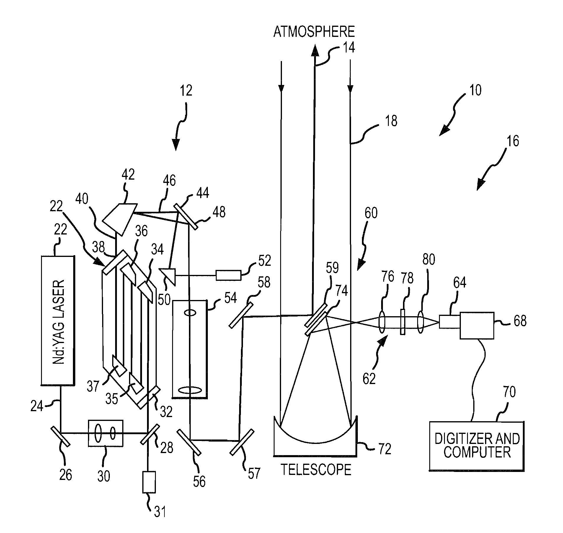
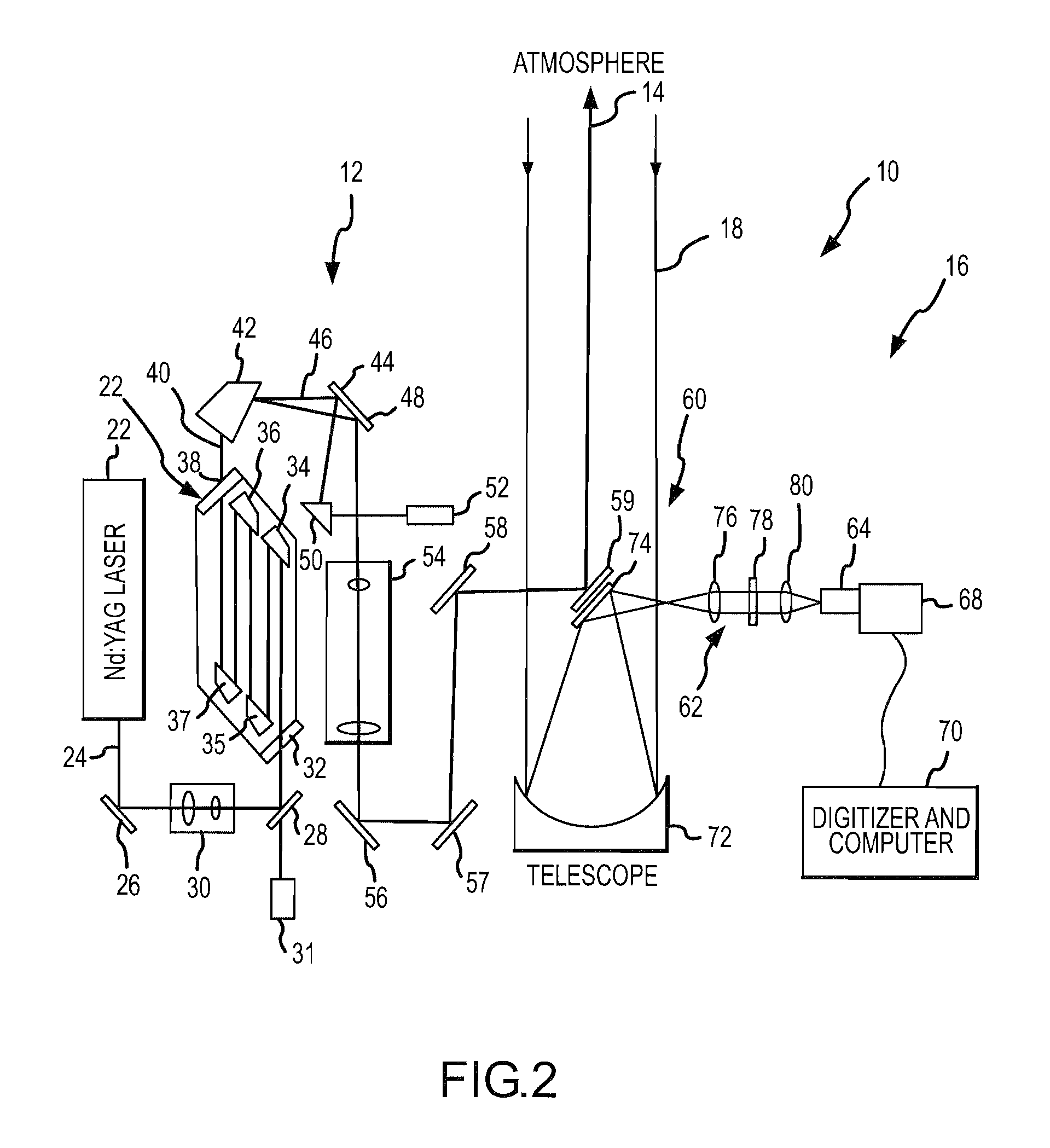
[0039]In the following description, the invention is set forth in the context of a high pulse energy, and Raman shifted Eye-safe Aerosol Lidar (REAL™) system. Indeed, the invention has a number of benefits and provides useful results in this regard. However, it will be appreciated that various aspects of the present invention are not limited to such lidar applications. Accordingly, the following description should be understood as exemplifying the invention and not by way of limitation.

[0040]Elastic backscatter lidars are useful tools for atmospheric researchers and potentially for commercial users because they are capable of showing the aerosol distribution in the atmosphere in both space and time. Although the backscatter return from these systems is typically uncalibrated, the images they provide are extremely valuable for identification of boundary layer depth, elevated aerosol layers, wave activity, and sources of pollution. Unfortunately, currently useful atmospheric aerosol l...


PUM


Abstract

An eye-safe atmospheric aerosol lidar featuring high transmit pulse energy to generate strong backscatter from long ranges in a single pulse together with an optically efficient receiver is disclosed. The transmitter employs a gas cell and non-focused laser beam geometry to convert short wavelength laser light to substantially safer and longer wavelength light by stimulated Raman scattering. The longer wavelength light is substantially safer than the shorter wavelength light thereby allowing the safe transmission of high energy pulses. The transmitter also features a diode injection seed and a beam expander which are effective to reduce the divergence of the long wavelength light below the field-of-view of the receiver. The receiver employs a telescope, collimating lens, interference filter, focusing lens, avalanche photodiode detector, amplifier and analog to digital converter. The transmit beam and receiver field of view are coaxial. Initial results demonstrate the ability of such technology to elucidate the structure of the atmosphere with high temporal and spatial resolution.

Description

GOVERNMENT SUPPORT[0001]The invention was made with Government support under Cooperative Agreement No. ATM-9820037 awarded by the National Science Foundation. The Government has certain rights in this invention.FIELD OF THE INVENTION[0002]This invention relates to laser radars or lidars in general and more particularly to an eye safe lidar suitable for scientific and commercial applications requiring long range and strong backscatter from a single or a small number of laser pulses such as scanning applications.BACKGROUND OF THE INVENTION[0003]Lidar has been an atmospheric research tool for over thirty years and within the last decade commercial systems have become available. Generally, these systems transmit laser energy into the atmosphere and detect backscattered radiation for analysis to identify particle aggregations and atmospheric structure of interest. Such systems have the potential to enable identification and imaging of aerosols, aerosol structures and the like at long dis...

Claims


Application Information

Patent Timeline
IPC IPC(8): G01C3/08G01N21/00
CPCG01N21/538G01S17/95G01S7/484G01S7/4811Y02A90/10
Inventor MAYOR, SHANESPULER, SCOTT
Owner UNIV FOR ATMOSPHERIC RES
Why Eureka
Try Eureka