Optical image measuring apparatus and optical image measuring method
a technology of optical image and measuring apparatus, which is applied in the field of optical image measuring apparatus and optical image measuring method, can solve the problems of not being able to accurately use the apparatus in fields that require high resolution images, the current available ccd camera cannot follow the beat frequency of a heterodyne, and the measurement fundamentals are difficult to shorten the measurement time in view of measurement fundamentals, etc., to achieve high precision, easy acquisition, and high precision
- Summary
- Abstract
- Description
- Claims
- Application Information
AI Technical Summary
Benefits of technology
Problems solved by technology
Method used
Image
Examples
first embodiment
[Structure of Apparatus]
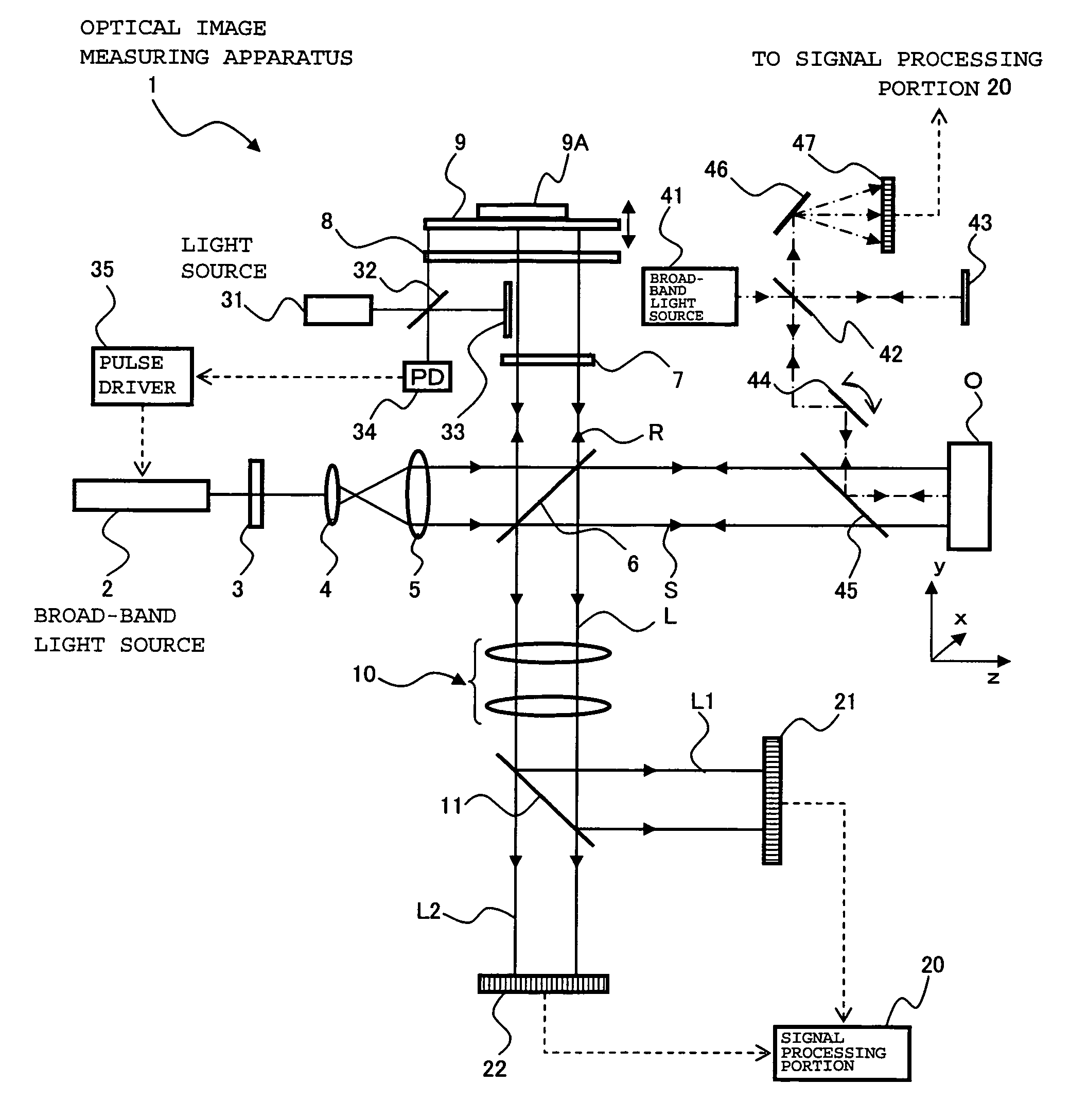
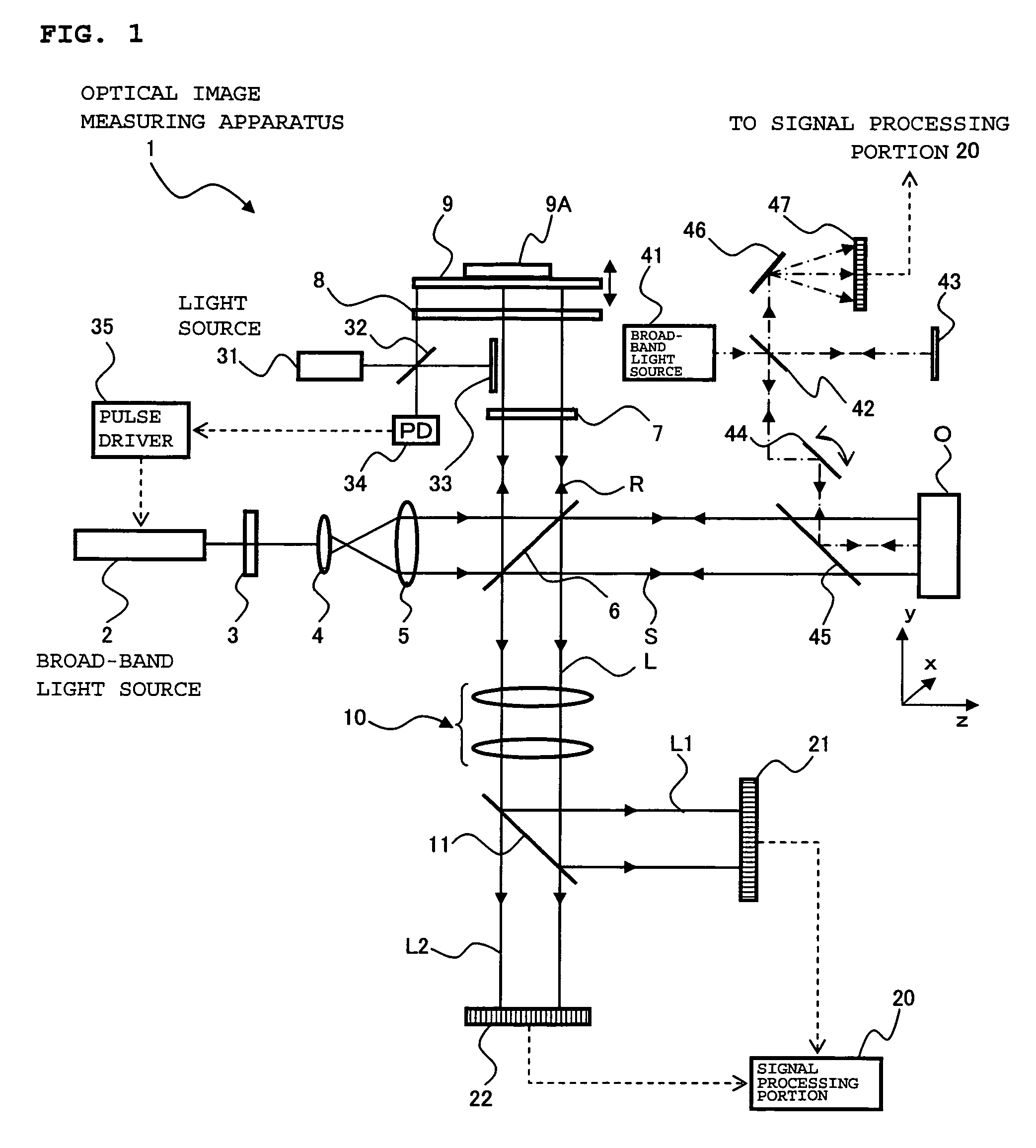
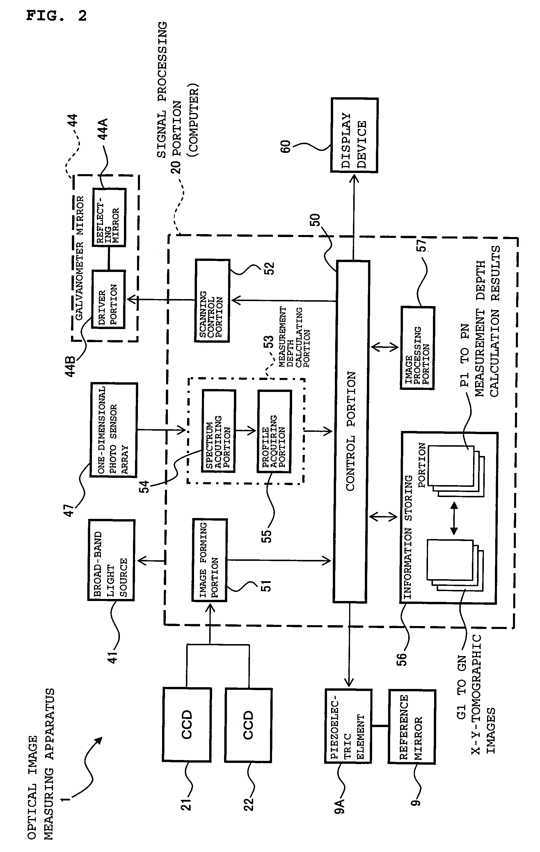
[0062]An optical image measuring apparatus according to the first embodiment of the present invention will be described with reference to FIGS. 1 and 2. FIG. 1 illustrates a schematic structure of an optical system of the optical image measuring apparatus according to this embodiment and FIG. 2 illustrates a structure of a control system thereof. The optical image measuring apparatus according to this embodiment is an apparatus used to form a tomographic image and a surface image of an object to be measured and a three-dimensional image thereof, for example, in the medical field and the industrial field. The object to be measured is an object which is made of a scattering medium such as a human eye, for example, in the medical field.
[Structure of Optical System]
[0063]First, referring to FIG. 1 the structure of the optical image measuring apparatus according to the embodiment is explained. The optical image measuring apparatus 1 includes a broad-band light sou...
modified examples
[0163]In the above-mentioned embodiment, the scanning with the auxiliary signal light is performed using the galvanometer mirror. However, the scanning means in the present invention is not limited to the galvanometer mirror and thus an arbitrary structure capable of suitably performing the scanning with the auxiliary signal light can be employed.
[0164]The wavelength filter is used as the combining and separating means in the present invention, for combining the auxiliary signal light with the signal light and separating the auxiliary signal light from the signal light. A beam splitter or the like can be alternatively used.
[0165]The one-dimensional photo sensor array is used as the auxiliary detection means in the present invention, for detecting the auxiliary interference light. For example, a two-dimensional photo sensor array such as a CCD may be used instead. In view of the precision of the formed three-dimensional image or the like, it may be desirable that a one-dimensional ph...
second embodiment
[0171]An optical image measuring apparatus according to a second embodiment of the present invention will be described. In the first embodiment, the light source (broad-band light source 41) different from the light source for image measurement (broad-band light source 2) is provided to acquire the measurement depth related to the X-y tomographic image. In contrast to this, in this embodiment, a part of interference light caused based on the light source for image measurement is detected to acquire the measurement depth related to the X-y tomographic image.
[0172]FIG. 7 illustrates an example of the optical image measuring apparatus according to this embodiment. An optical image measuring apparatus 100 shown in FIG. 7 has substantially the same structure as that of the optical image measuring apparatus 1 according to the first embodiment. In FIG. 7, same reference symbols are provided to the same constituent portions as those in FIG. 1.
[0173]The optical image measuring apparatus 100 ...
PUM
 Abstract
Description
Claims
Application Information
 - R&D
- Intellectual Property
- Life Sciences
- Materials
- Tech Scout
- Unparalleled Data Quality
- Higher Quality Content
- 60% Fewer Hallucinations
Browse by: Latest US Patents, China's latest patents, Technical Efficacy Thesaurus, Application Domain, Technology Topic, Popular Technical Reports.
© 2025 PatSnap. All rights reserved.Legal|Privacy policy|Modern Slavery Act Transparency Statement|Sitemap|About US| Contact US: help@patsnap.com


