
Total impedance and complex dielectric property ice detection system

Inactive Publication Date: 2008-10-21
JARVINEN PHILIP ONNI
View PDF45 Cites 59 Cited by
  • Summary
  • Abstract
  • Description
  • Claims
  • Application Information

AI Technical Summary

Benefits of technology

[0014]All subsystems and support units, including the impedance measurement subsystem, utilize low power consumption, miniaturized electronic chips or components whose vertical dimensions are a few millimeters in height. Because of the miniature size and minimal heights of all elements, they are collocated directly with the ice sensor in a thin, pliant planar patch of diminished area which may be mounted anywhere on the aircraft and which has little effect on the aircraft's drag or flowfield. The present patent offers for the first time a unique design which collocates the ice sensor subsystem physically with the impedance measurement and readout units and all other supporting components. Collocation of all subsystems and supporting units eliminates the long wire and coaxial cable runs between components needed by prior approaches. In the present invention, wire and coaxial cable lengths are measured in distances of a few centimeters or less since all components are collocated together while in prior art patents, external sensors on the aircraft were connected to the rest of the system which had to be mounted far away either internal to the wing or inside the fuselage because of their large physical size. Thus prior patent implementations were required to use wire and coaxial cable runs with lengths from near a meter to fifteen meters or more. Thus collocation as done in the present patent provides significant weight savings because of shorter wire and coaxial cable lengths used and improves the accuracy of the impedance and dielectric measurements because deleterious cable effects are eliminated.
[0030]It is a further objective of the present invention that the ice sensor system be designed and constructed from newly available, highly accurate, low cost, low profile, miniature electronic chips, electronic components and devices; the selected components having vertical heights in the range of a few millimeters.
[0031]It is a further objective of the present invention that all parts, subsystems and subunits of the ice detection system be collocated with the ice sensor in a thin, pliant, planar patch of minimal height and area which does not significantly effect the drag of the aircraft or the aircraft flowfield. Collocation provides substantial savings in sensor system cost and weight along with significant improvements in the accuracy of the measurements of total impedance values because of the reductions in interconnect wire and coaxial cable lengths with associated reductions in cable effects on measured signals.

Problems solved by technology

In addition, complex dielectric measurement algorithms identify whether cracks, flaws, or voids or increased electrical conductivity exist in the ice covering the sensor from their effects on the shape and size of the measured complex dielectric locus or from the length of the vector at the pre-selected frequency.

Method used


Image

  • Total impedance and complex dielectric property ice detection system
  • Total impedance and complex dielectric property ice detection system
  • Total impedance and complex dielectric property ice detection system

Examples


Embodiment Construction

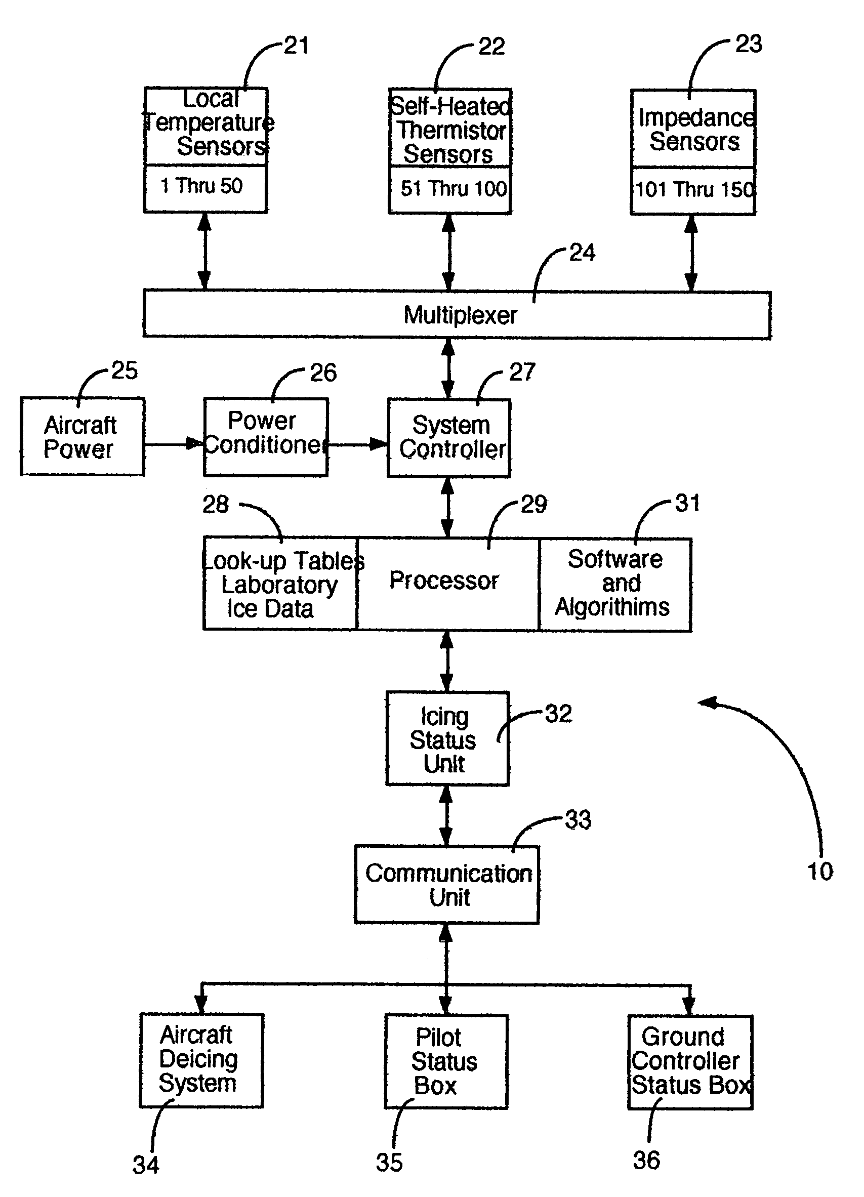
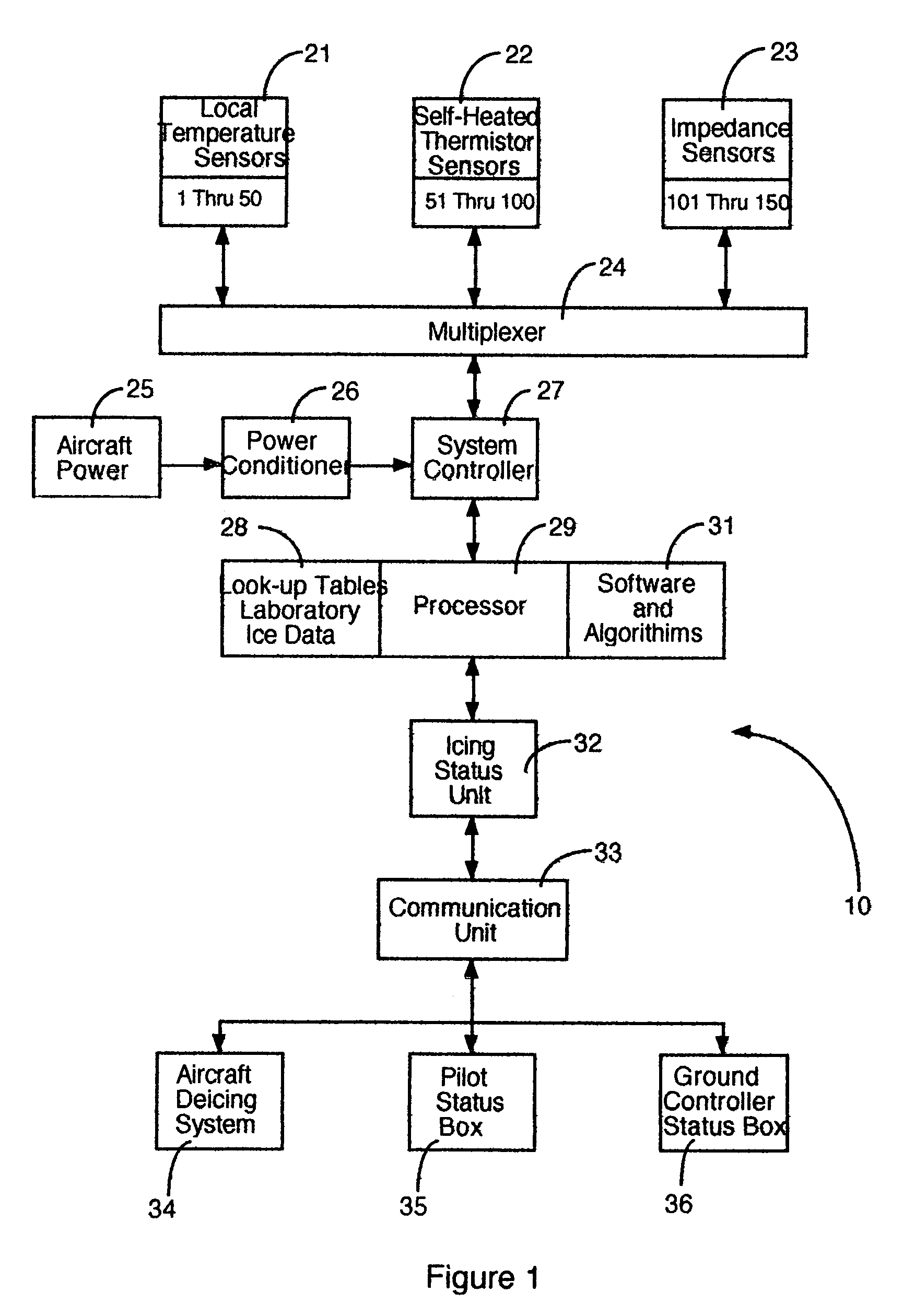
[0056]Referring now to the drawings and in particular to FIG. 1, the present invention discloses the block diagram 10 which includes local temperature sensors 21, self-heating thermistor sensors 22 for measuring thermal conductivity of the contaminant and impedance sensors 23. Additional elements include a multiplexer 24, system controller 27, and a processor 29 with software and algorithm sections 31 and look-up tables 28 containing laboratory measured properties of ice. The processor and its associated support sections processes the measured data to determine that atmospheric and aircraft surface temperature conditions are appropriate for icing. The processor constantly operates on data in search of the start of contaminant accreation and then discriminates between accreating types of possible contaminants including ice, rain water, deicing fluid, or snow based on the thermal conductivity value measured by the self-heated thermistor along with measured dielectric properties. When ...


PUM


Abstract

An ice detection system that detects the onset of ice accreation on an aircraft's external surfaces, continuously measures its thickness and growth time history and provides the type of ice, glaze or rime, is disclosed along with an independent way to confirm that the contaminant is known to be ice and only ice. Total impedance data, thermal conductivity value and complex dielectric properties are used to discriminate between ice, water, deicing fluid and snow with measurements made by low cost, low power consumption, low profile, miniature electronic chips, components and devices collocated together on the external surface in a thin pliant patch that does not effect the airflow about the aircraft. The ice detection system provides ice accreation data and warning signals to displays and aural signaling devices in the cockpit for the pilot and to the control console of a ground controller flying the aircraft if it is unmanned.

Description

COPYRIGHT NOTICE[0001]A portion of the disclosure of this patent document contains material that is subject to copyright protection. The copyright owner has no objection to facsimile reproduction of the patent document or the patent disclosure, as it appears in the Patent and Trademark Office patent file or records, but otherwise reserves all copyright rights whatsoever.FIELD OF THE INVENTION[0002]The invention relates to the field of ice detection on an aircraft in flight or on the ground prior to takeoff using total impedance, thermal conductivity and complex dielectric property measurements.BACKGROUND OF INVENTION[0003]The fatal crash of a commercial airliner, American Eagle Flight 4184, an ATR-72 aircraft, on Oct. 31, 1994 near Roselawn, Ind. with the loss of all 68 on-board and the more recent crash on Feb. 16, 2005 of a Cessna Citation corporate jet owned by Circuit City during approach to the Pueblo, Colo. airport killing the two pilots and six other people on-board, both eve...

Claims


Application Information

Patent Timeline
IPC IPC(8): G08B21/00
CPCB64D15/20
Inventor JARVINEN, PHILIP ONNI
Owner JARVINEN PHILIP ONNI
Learn More