Method and apparatus for calendering a paper or paperboard web

a technology of paper or paperboard and calender, which is applied in the direction of press section, manufacturing tools, non-fibrous pulp addition, etc., can solve the problems of poor thermal stability, damage to the coating, and breakage of the operation of the calender, and achieve the effect of easy calendering

Inactive Publication Date: 2008-10-21
VALMET TECH INC
View PDF15 Cites 1 Cited by
  • Summary
  • Abstract
  • Description
  • Claims
  • Application Information

AI Technical Summary

Benefits of technology

[0009]Consequently, the aim of the present invention is to provide a method for calendering a paper or paperboard web by which the above-mentioned problems can be avoided and the edge areas of the web can be easily calendered without a separate, space-consuming counter roll installed for edge calendering. It is also an aim of the invention to provide a device implementing the aforementioned method.
[0010]The invention is based on the idea that the outer edges of the paper or paperboard web, i.e. the edge areas, are calendered in the reeling step following the calendering step. At least one calendering nip is provided, preferably two calendering nips, one for each edge of the web. The calendering nips are formed by means of a reeling cylinder in a reel-up and two calendering rolls which are shorter than the width of the web. The web is led to the reeling cylinder in such a way that the uncalendered web areas of the web are passed through the calendering nips. In this way, the edge areas of the web can be easily calendered by utilizing the reeling cylinder already existing in the paper machine, wherein no separate, space-consuming counter roll will be needed for the edge calendering.

Problems solved by technology

Variable-crown rolls and polymer rolls are coated with a soft polymer coating which is normally made of an epoxy with a poor thermal stability.
Consequently, in a nip in which one roll is a heated thermo roll and the other one is a roll coated with a soft coating, one must take care that the coating of the coated roll does not touch the thermo roll, which could result in a damage of the coating.
A damaged roll must be replaced with a new one, which causes a break in the operation of the calender and increases the maintenance costs of the device.
Furthermore, the strips cut off from both edges of the web, which are conveyed to a pulper, increase the quantity of waste from the paper machine.
One problem in this arrangement is the fact that the roll arrangements required by the edge calendering consume space in the calendering device.

Method used


Image

  • Method and apparatus for calendering a paper or paperboard web
  • Method and apparatus for calendering a paper or paperboard web
  • Method and apparatus for calendering a paper or paperboard web

Examples


Embodiment Construction

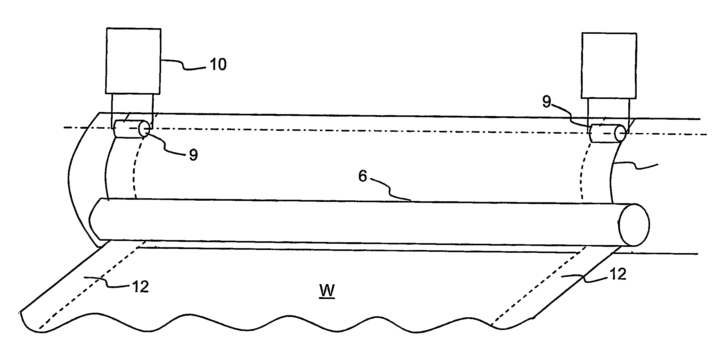
[0017]In this application, the roll length refers to the length of the shell of the roll in question, in its axial direction. The web width refers to the width of the paper or paperboard web in its cross direction. Furthermore, in this application, the term paper or paperboard web refers to paper, paperboard and tissue paper webs.

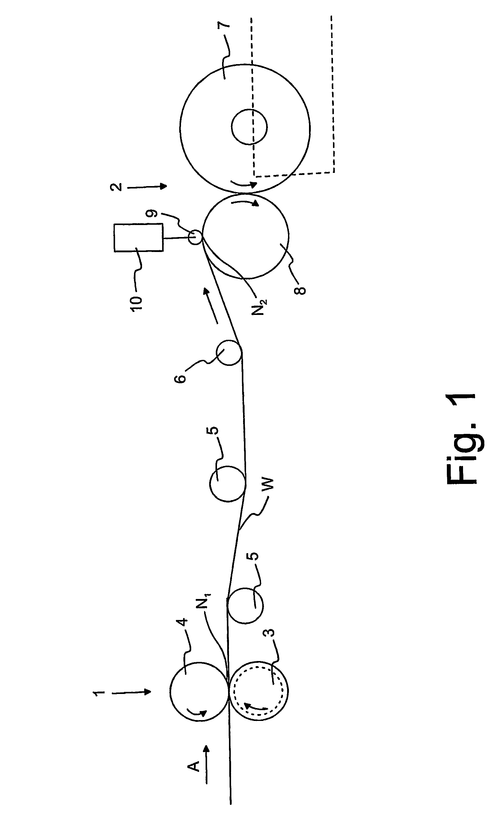
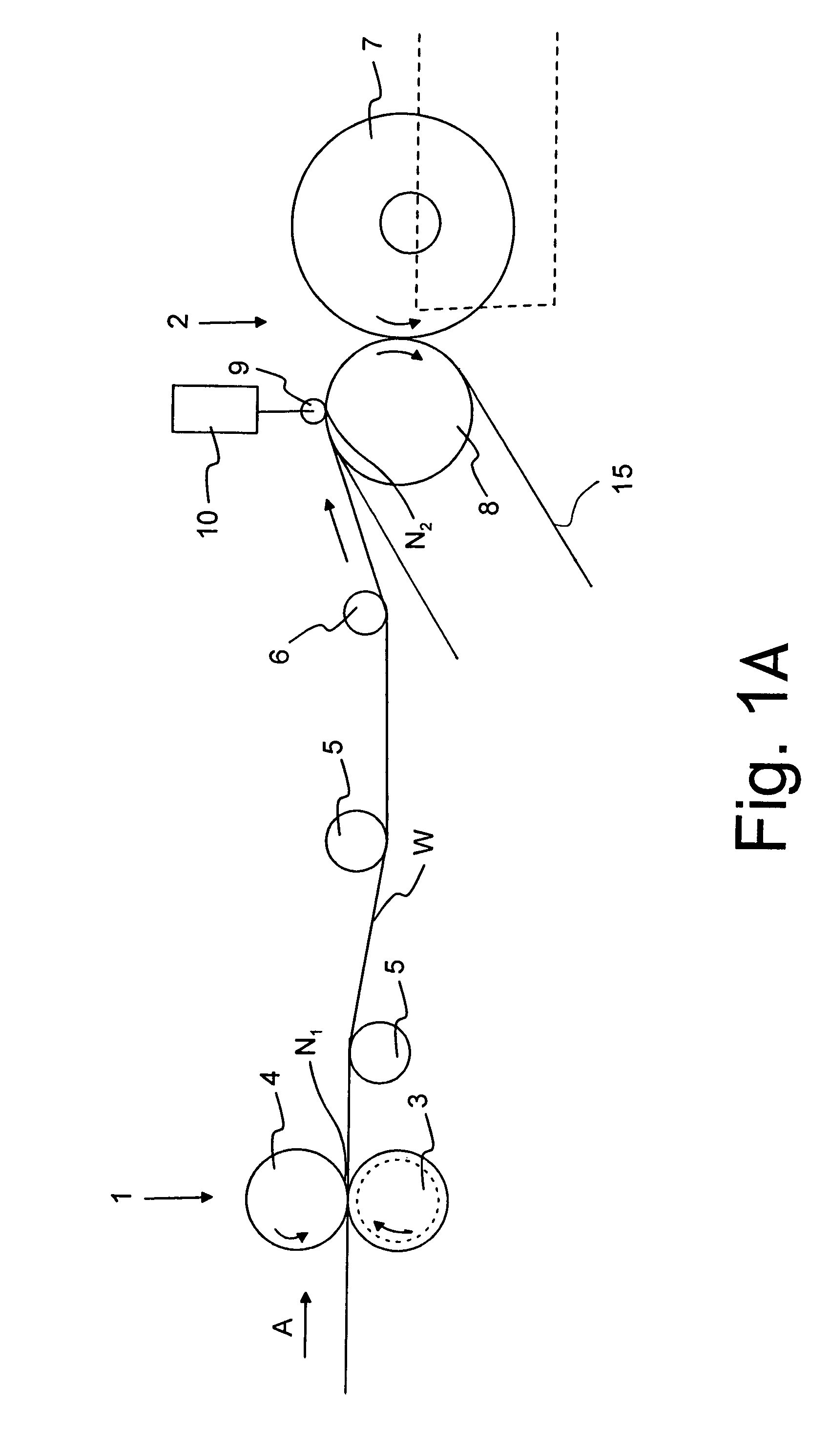
[0018]FIG. 1 shows, in a schematic side view, a device for calendering a paper or paperboard web W. The web W is introduced in the calendering step 1 in the direction of an arrow A either directly from papermaking (so-called on-line calendering) or from an unwinder (so-called off-line calendering). The calendering step 1 comprises a nip N1 formed by a soft coated roll 3 and a hard-faced heated roll 4, through which nip the web to be processed is introduced. Depending on the web to be calendered and its use, the calendering step may also comprise several calendering nips which may be formed of different rolls. It is essential that at least one nip is formed ...


PUM

PropertyMeasurementUnit
edge areaaaaaaaaaaa
areasaaaaaaaaaa
widthaaaaaaaaaa

Abstract

A method and a device for calendering a paper or paperboard web, in which the web is led first into a calendering step and then into a reeling step. At least one edge area of the web is calendered separately in the reeling step.

Description

CROSS REFERENCES TO RELATED APPLICATIONS[0001]This application is a national stage application of International App. No. PCT / FI2004 / 050097, filed Jun. 17, 2004, the disclosure of which is incorporated by reference herein, and claims priority on Finnish App. No. 20030913, filed Jun. 18, 2003.STATEMENT AS TO RIGHTS TO INVENTIONS MADE UNDER FEDERALLY SPONSORED RESEARCH AND DEVELOPMENT[0002]Not applicable.BACKGROUND OF THE INVENTION[0003]The invention relates to a method for calendering a paper or paperboard web and to a device for implementing the aforementioned method.[0004]In connection with papermaking, after the drying of the paper web, the web is subjected to calendering as a normal finishing step. There are many calendering methods, but it is common to all of them that the web is led through one or more nips formed between two surfaces, typically between rotating roll surfaces. The purpose of the calendering is to improve the quality of the paper by pressing it to a particular st...

Claims


Application Information

Patent Timeline
Patent Type & Authority Patents(United States)
IPC IPC(8): D21G1/00
CPCD21G1/00
Inventor KIRVESKARI, ERKKI
Owner VALMET TECH INC
Why Eureka
Try Eureka