Steel plate surface blind hole punching die

A stamping die and blind hole technology, which is applied in the field of blind hole stamping dies on the surface of steel plates, can solve the problem of low qualified rate of blind holes in stamped thin steel plates, difficulty in ensuring the overall alignment accuracy of the punch and die, and the time required for adjustment and check Long and other issues, to avoid damage to stamping equipment, to achieve the effect of possibility and reliability, and small deformation

Inactive Publication Date: 2012-12-12
CHENGDU ZHONGHONG RAIL TRANSIT ENVIRONMENTAL PROTECTION IND
View PDF9 Cites 0 Cited by
  • Summary
  • Abstract
  • Description
  • Claims
  • Application Information

AI Technical Summary

Problems solved by technology

If a crank connecting rod punch is used, since there is no pressure relief and oil return system of the hydraulic mechanism at the bottom point of the stroke, the joints of the equipment will have a straightening posture, and the result will either damage the equipment or smash the mold. When the mold is manufactured by the machining center, the overall alignment accuracy of the punch and die is difficult to guarantee when it is installed on the punching machine, and it takes a long time to adjust and check, which directly leads to the low quality pass rate of the blind hole products of stamping and forming thin steel plates

Method used


Image

  • Steel plate surface blind hole punching die
  • Steel plate surface blind hole punching die
  • Steel plate surface blind hole punching die

Examples


Embodiment Construction

[0020] The present invention is further described by the following examples. This example is only used to further illustrate the present invention, but it cannot be interpreted as limiting the protection scope of the present invention. Essential improvements and adjustments belong to the protection scope of the present invention.

[0021] combine Figure 1 to Figure 4 .

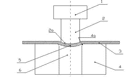
[0022] As shown in the figure, the stamping die for blind holes on the steel plate surface includes a punch 2 installed on the punch of the punch and a die 4 installed on the base of the punch. The center of the die 4 is a through hole 5 . The cylindrical diameter of the punch 2 is smaller than the diameter of the central hole 6 of the die. The cylinder diameter of the punch 2 is equal to the inner diameter of the blind hole 5 minus twice the thickness of the steel plate 3 . The impact surface 2a of the impact head of the punch 2 is arc-shaped.

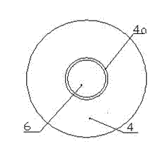
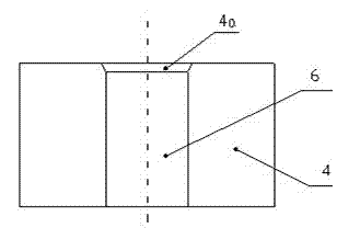
[0023] combine figure 1 , figure 2 and image 3 , figu...


PUM


Abstract

The invention discloses a steel plate surface blind hole punching die. The steel plate surface blind hole punching die comprises a convex die installed on a plunger chip of a punch, and a concave die arranged on a punch base, wherein a through hole is formed in the centre of the concave die; the diameter of a column of the convex die is less than that of the hole in the centre of the concave die; and the impacting surface of an impacting head of the convex die is arc shaped. According to the steel plate surface blind hole punching die, the freedom degree on the direct contact between a lower stopping point of the convex die and a lower forming part of a blind hole of the concave die is released, and therefore, the surface of a steel plate is stretched to be formed within an elastic range through a material, so that the wear of the die is reduced, the work hardening is achieved, the mechanical performance of a product is improved, the rigid contact of the convex die and the concave die is avoided, punching equipment is avoided being damaged, the feasibility and the reliability in the rigid punching production are achieved, and the service life of the die is prolonged; after the improvement on the die, the arc-shaped concave pit type blind hole processed by the concave die can be formed relatively precisely, and has low deformation, and the cost of processing is relatively low.

Description

[0001] technical field [0002] The invention belongs to the technical field of metal material processing, in particular to the technical field of metal material calendering processing, and particularly relates to a blind hole stamping die on the surface of a steel plate. Background technique [0003] Blind hole is a pit that connects the surface layer and the inner layer without penetrating, such as the dense blind hole surface of a golf ball, which can reduce the small air vortex resistance on the surface when the golf ball is moving at high speed. The conduction of sound waves also plays a very important role. [0004] At present, blind holes on the surface of thin steel plates are formed by hydraulic punching presses, which are usually formed by punches installed on the head of the punch punching the thin steel plates placed on the die. The center of the die is a pit designed according to the requirements of blind holes. When the die impacts the steel plate, it directly...

Claims


Application Information

Patent Timeline
IPC IPC(8): B21D37/10B21D22/04
Inventor 王力张噶
Owner CHENGDU ZHONGHONG RAIL TRANSIT ENVIRONMENTAL PROTECTION IND
Why Eureka
Try Eureka