
Article having a birefringent surface and microstructured features having a variable pitch or angles for use as a blur filter

a technology of microstructured features and birefringent surfaces, which is applied in the field of articles having birefringent surfaces and microstructured features having a variable pitch or angle for use as blur filters, can solve the problems of rainbow-like color distortion and other artifacts in the displayed digital image, induced photographic color distortion and color banding in digital imaging,

Inactive Publication Date: 2008-08-26
3M INNOVATIVE PROPERTIES CO
View PDF155 Cites 29 Cited by
  • Summary
  • Abstract
  • Description
  • Claims
  • Application Information

AI Technical Summary

Benefits of technology

The present invention relates to a blur filter for use in optical devices such as cameras and image sensors. The blur filter includes a body with first and second surfaces and first and second in-plane axes. The body has a structured surface with a variable pitch or angle between the in-plane axes. The structured surface spreads a light signal in the optical path into multiple light signals when incident upon the image sensor. This results in a blurred image with improved clarity and reduced blurring. The blur filter can be used in a variety of optical devices and can be designed to provide a specific level of blur.

Problems solved by technology

Photographic color distortion and color banding in digital imaging are induced by the interaction between image patterns and image color sensor patterns.
These undesirable effects are a consequence of having repetitive image features on order of the size of the individual pixel sensors and from sharp edges representing an abrupt change in color.
Typically, this causes the colors to cycle and results in rainbow-like color distortions and other artifacts in the displayed digital image, often referred to as moiré effects.
Of these approaches, digital computational post-processing methods include using software such as the ADOBE PHOTOSHOP program, requiring that a user manually resolve the color moiré through digital filters and selection, an often time-consuming and cumbersome approach that can require a high degree of expertise and results in a degraded image.
Performing post-processing within the camera requires a powerful microprocessor and large amounts of working memory, contrary to low-cost and fast picture taking.
Modifying the sensor array to solve the moiré effects is also a viable, although expensive, approach and is not guaranteed to resolve the effects.
However, instead of eliminating the moiré effects, the hexagonal sensor arrangement changes the patterns to which it is sensitive, causing other undesirable effects.
However, this approach can result in high manufacturing costs and difficult reliability issues, requiring an integrated circuit having a trilayer stack of transistors, each of which operates within very tight specifications.
Also, the quartz plates can be expensive for certain implementations and tend to break easily, making them difficult to handle and not particularly well-suited to mobile devices.
The diffraction grating modifies the phase relationships in the incoming light and creates a pattern of constructive and destructive interference.
An undesirable effect occurring in image sensors includes anomalous variations in intensity resulting from diffraction of the incoming light signal, and arising, for example, from higher order diffraction peaks.
The difficulty with this approach is that for small pitches, the solutions only optimize for single wavelengths; thus, diffraction can be eliminated for the color red, for example, but may still be severe for the color blue.
However, with large pitches (e.g., 250 microns) the groove depth becomes deeper (e.g., 26 microns) and begins to project onto the sensor imaging surface, an undesirable situation.

Method used


Image

  • Article having a birefringent surface and microstructured features having a variable pitch or angles for use as a blur filter
  • Article having a birefringent surface and microstructured features having a variable pitch or angles for use as a blur filter
  • Article having a birefringent surface and microstructured features having a variable pitch or angles for use as a blur filter

Examples


example 1

Creation of Oriented Microstructured Film

[0171]A polyethylene terephthalate (PET) with an inherent viscosity (I.V.) of 0.74 available from Eastman Chemical Company, Kingsport, Tenn. was used in this example.

[0172]The PET pellets were dried to remove residual water and loaded into an extruder hopper under a nitrogen purge. The PET was extruded with an increasing temperature profile of 232° C. to 282° C. within the extruder and the continuing melt train through to the die set at 282° C. Melt train pressures were continuously monitored and an average taken at the final monitored position along the melt train prior to bringing the die into close proximity to the tool onto which the polymer film is formed simultaneously with the structuring of a first surface of that film against the tool.

[0173]The tool was a structured belt Nickel alloy specific composition unknown, made at 3M, electroformed, welded sections having a negative version of the structured surface formed on the cast film. Th...

example 2

Variable Pitch Blur Filter with White Light Source

Sample Preparation

[0180]The tooling was cut by diamond turning copper sheeting on a 3M Pneumo. No oil or liquid cooling was used. The diamond used had an 84 degree included angle and was held so as to yield a cut with a 6 degree angle off of horizontal with a vertical facet sidewall. The cut tool was treated with BTA. Unoriented PET cast films were then embossed in a compression molding machine. The process conditions varied depending upon the material being molded. Conditions were chosen such that high fidelity replication was achieved while avoiding crystallization induced haze. If a sample displayed haze that was discernible to the eye that sample was discarded. Sometimes it was found to be helpful to use an ice bath to rapidly cool the film.

[0181]Samples were then cut to size and uniaxially oriented in a commercial lab scale batch tentering machine. Draw conditions varied depending upon the material, the thickness, and the target...

example 3

Variable Pitch Blur Filter with Laser Light Source

Sample Preparation

[0185]A sample was prepared as explained in Example 2. The film was PET with an embossed 6° sawtooth structure with pitch variation.

Sample Test

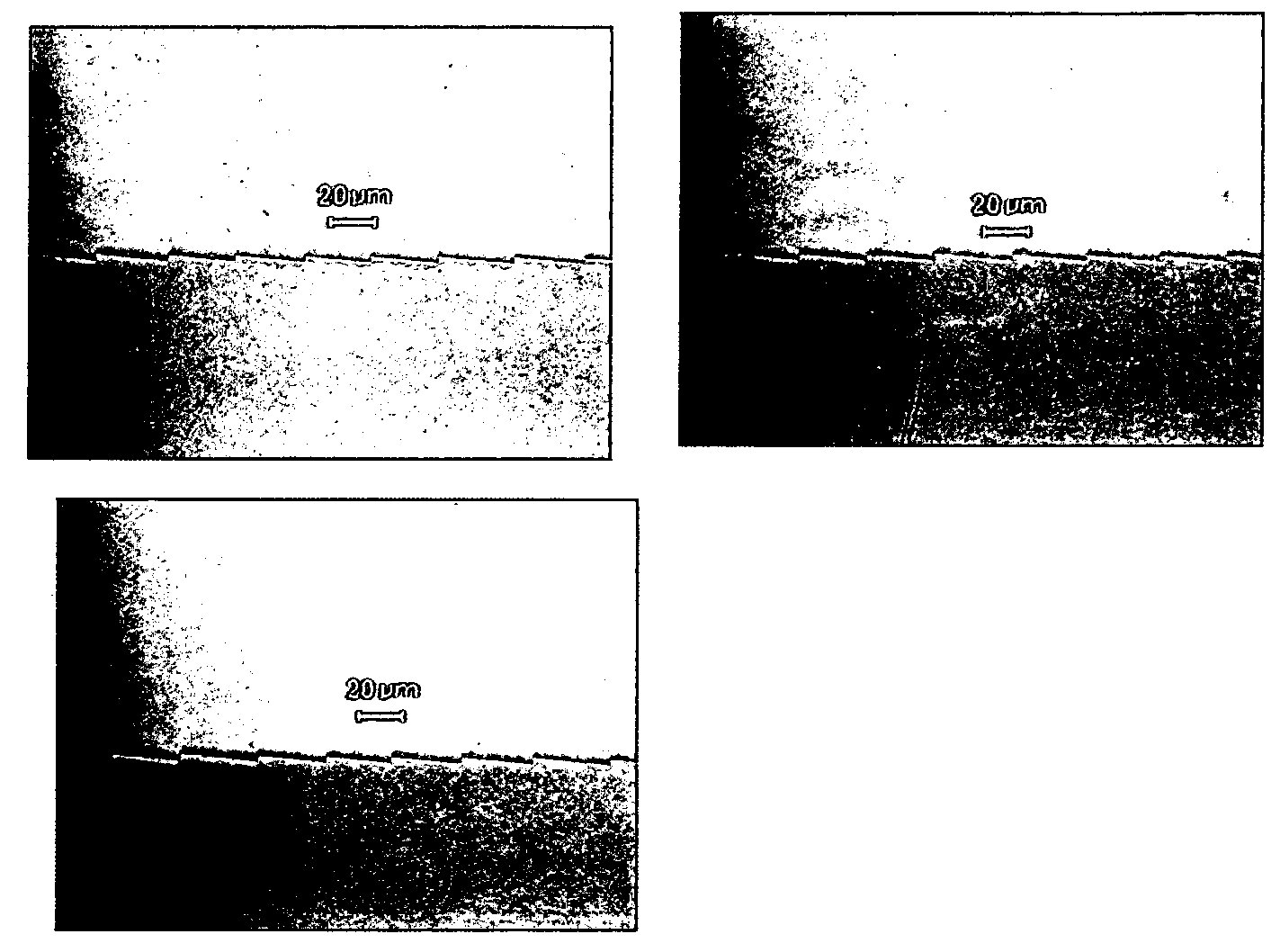
[0186]The test set-up was the same as in Example 2, except that a green laser was used as the light source instead of the white light source. When viewing the resulting image, diffractive artifacts were reduced in the 10% random pitch sample and even more reduced in the 100% random pitch sample.

[0187]

Camera Conditions for Example 3Picture 3aPicture 3b(10% random pitch)(100% random pitch)Camera Manufacturer: KonicaCamera Manufacturer: KonicaMinolta Camera, Inc.Minolta Camera, Inc.Camera Model: DiMAGE A2Camera Model: DiMAGE A2Software: DiMAGE A2 Ver.1.10Software: DiMAGE A2 Ver.1.10Date / Time: 2005:06:08 15:56:05Date / Time: 2005:06:08 16:00:22YCBCr Positioning: CenteredYCBCr Positioning: CenteredExposure Time: 1 / 200 secExposure Time: 1 / 200 secF Number: 11.0F Number: 11.0Exposure P...


PUM


Abstract

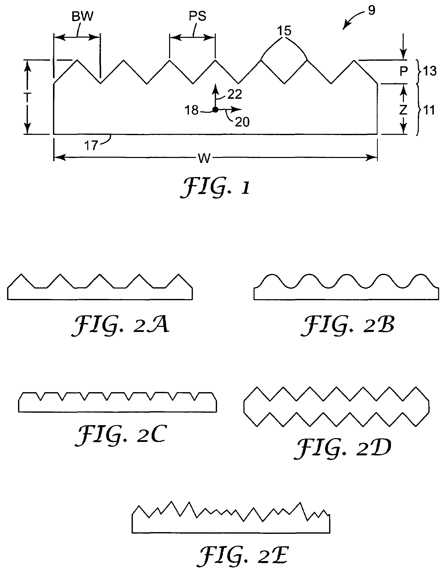
An optical low pass filter or blur filter, and method of making the filters, using an article having a birefringent surface for refracting incoming light when used with an image sensor. The birefringent surface of the article, such as a film, is structured or tilted such that, when the blur filter is placed within an optical path between a lens and the image sensor, the birefringent surface causes refraction of a light signal in the optical path into multiple light signals each being incident upon different sub-pixels within the pixels in the image sensor to prevent or reduce artifacts, such as undesirable color moiré effects, in the resulting digital image. The structures on the surface have a variable pitch or angles. The variable pitch can include a periodic, aperiodic, or quasi-aperiodic pitch, to reduce diffractive artifacts in the resulting image.

Description

FIELD OF INVENTION[0001]The present invention relates to an article having a birefringent surface with variable pitch or angle microstructures for use as a blur filter with image sensors in order to reduce artifacts in a resulting image.BACKGROUND[0002]Photographic color distortion and color banding in digital imaging are induced by the interaction between image patterns and image color sensor patterns. These undesirable effects are a consequence of having repetitive image features on order of the size of the individual pixel sensors and from sharp edges representing an abrupt change in color. Since real-world pattern spacing never quite matches the digital sensor patterns, the color that is overweighted will vary spatially through the picture in correspondence to how out of phase the two patterns are from each other. Typically, this causes the colors to cycle and results in rainbow-like color distortions and other artifacts in the displayed digital image, often referred to as moiré...

Claims


Application Information

Patent Timeline
Patent Type & Authority Patents(United States)
IPC IPC(8): G03B7/099G02B27/28G03B17/18H04N5/335H04N9/083G02B27/46H04N9/03
CPCG02B5/1833G02B27/46G02B5/1866
Inventor BIERNATH, ROLF W.BROTT, ROBERT L.MERRILL, WILLIAM WARDHUIZINGA, JOHN S.BLACK, WILLIAM B.
Owner 3M INNOVATIVE PROPERTIES CO
Learn More