
Apparatus and process for preparing crystalline particles

a technology of apparatus and crystalline particles, applied in the field of apparatus for preparing crystalline particles, can solve the problems of micronisation and milling processes, micronisation or milling products may be more susceptible to moisture uptake than crystalline products, and general product loss, etc., to achieve efficient and economical, reduce hazards, and reduce size

Inactive Publication Date: 2008-06-10
GLAXO GROUP LTD
View PDF13 Cites 6 Cited by
  • Summary
  • Abstract
  • Description
  • Claims
  • Application Information

AI Technical Summary

Benefits of technology

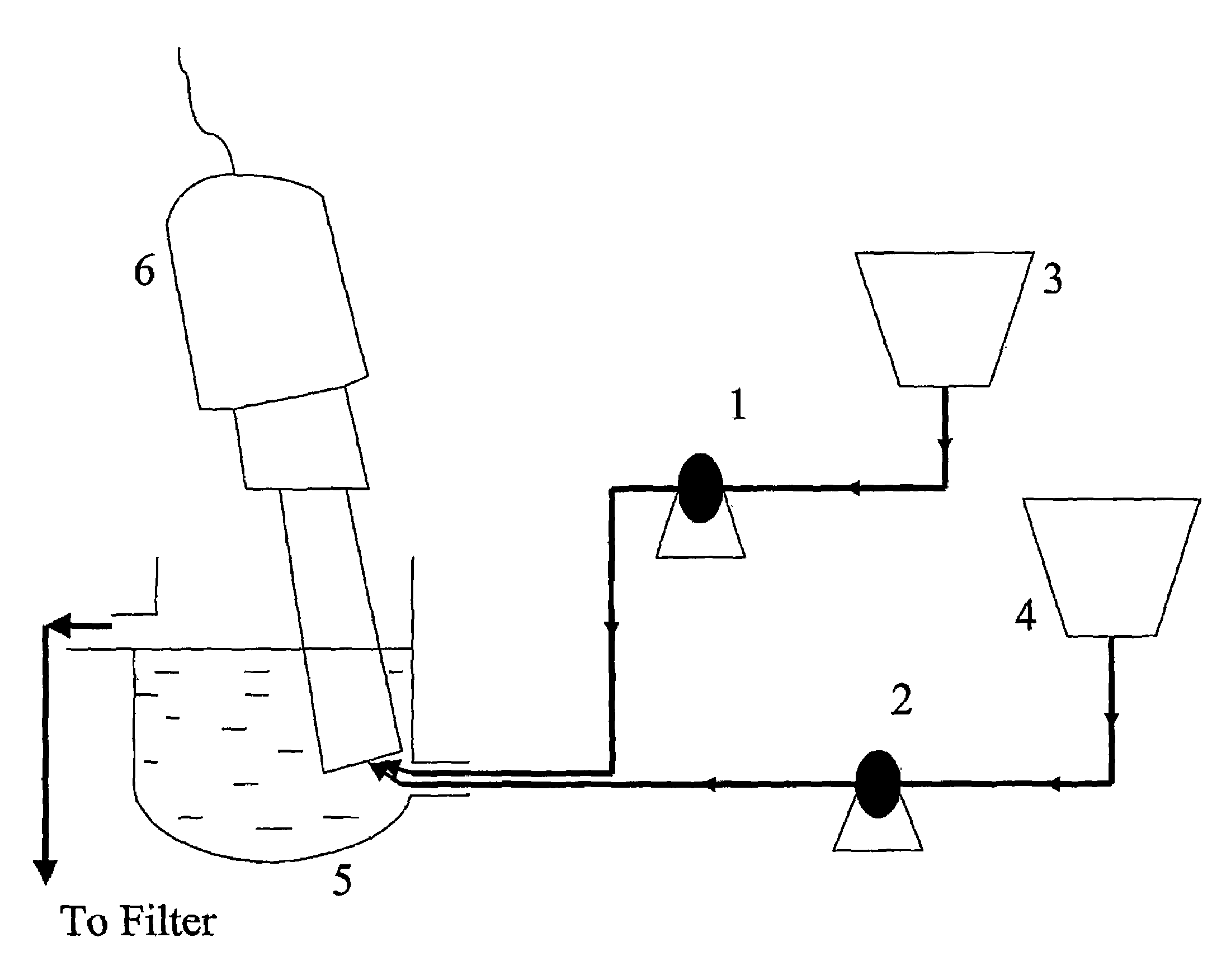
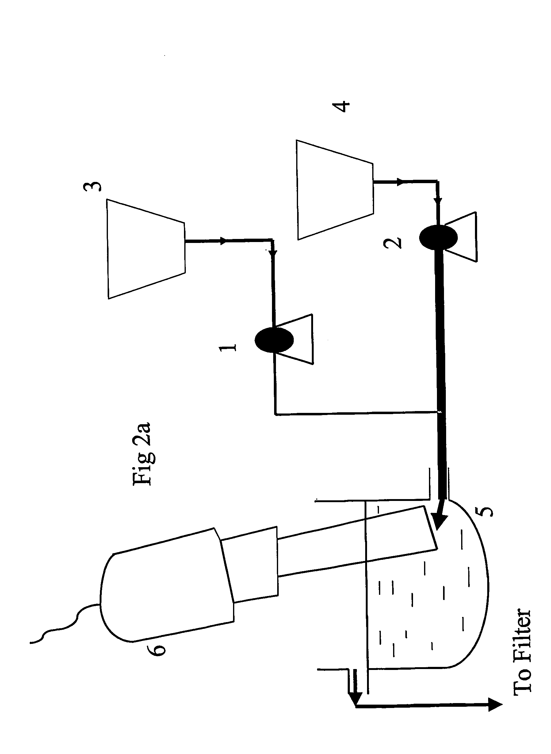
[0012]The advantages of the invention include the fact that the process is capable of running continuously (subject to adequate supply of solution and anti-solvent) even if, for a particular application, it may be desired to run it only for a relatively short time. Also since the process is an essentially “wet” process it significantly reduces hazards associated with dry particulate matter. A feature of the process is that in a steady state the concentration of dissolved substance in the mixing chamber of the flow cell remains approximately constant since the precipitating substance is replaced by the inflow of further solution. This allows the process to be run continuously and reproducibly. We have found that the process according to the invention is capable of being very efficient and economical with product yields of up to 95-98%.
[0013]The present process has advantages over that described in WO 00 / 38811 in that it is capable of generating particles of smaller size, in particular particles in the low micron range, especially particles of size less than 2 microns.
[0029]Shearing effects are undesirable since they will vary from one agitator type to another and will tend to reduce the predictability of the particle size and shape.
[0032]Preferably the outlet port of the apparatus is disposed above the inlet ports in the mixing chamber such that the liquid in the mixing chamber flows from a lower to a higher point in the chamber before exiting. This arrangement optimises mixing and allows ready balance of the rates of inflow and outflow.
[0034]The position of the outlet port relative to the inlet ports is believed to have an influence on the size of the crystalline particles generated. Without being limited by theory, it is believed that the greater the distance between the inlet ports and outlet port, the greater the average residence time of the particles in the flow cell, the longer the crystalline particles have to mature. When particle maturation is permitted to take place in the vessel this may be advantageous if it reduces the likelihood of downstream blockages.
[0081]The advantages that the invention may possess include the fact that the process may be performed in a continuous manner without requirements for batch processing, that process may be scaled up with relative ease and that the apparatus and process are capable of producing particle size distributions of very high uniformity index (defined as D10 / D90×100) and particles of size in the low micron range.

Problems solved by technology

However, there are a number of disadvantages associated with milling and micronisation processes including that the fraction having the desired particle size may be relatively small, that there may be generated a significant fraction of particles that are finer than is desired (which may be deleterious e.g. if it affects bioavailability) and that product losses generally may be considerable (e.g. through coating of the machinery).
This may be undesirable when there exists a tendency for the amorphous regions to convert to a crystalline state.
Furthermore micronised or milled products may be more susceptible to moisture uptake than crystalline products.
Micronisation and milling processes also suffer from the disadvantages that they are relatively energy intensive and require containment and other measures to avoid the risk of dust explosion.
Rapid precipitation (e.g. by dilution of a solution with an anti-solvent) may give rise to crystalline particles which could be of suitable size, however this technique is notoriously difficult to control and has not found widespread acceptance in the pharmaceutical industry, particularly in relation to inhalation products.

Method used


Image

  • Apparatus and process for preparing crystalline particles
  • Apparatus and process for preparing crystalline particles
  • Apparatus and process for preparing crystalline particles

Examples


example 1

Distributions of Particles of Crystalline Fluticasone Propionate

Experimental Procedure

[0103]The drug substance (fluticasone propionate, FP) (1 wt) was dissolved in acetone (15-20 vols, according to experiment) by heating to 56° C. and then allowed to cool to between 25 and 35° C. A first peristaltic pump was connected to the said FP / acetone solution and a second peristaltic pump was connected to a water reservoir wherein the water was in the temperature range of about 3-30° C. Prior to starting the pumps the mixing chamber was filled with a solution of acetone and water (the ratio of each being the same as the relative pumping rates from the two reservoirs). By doing this, the relative concentrations of the water to acetone remained constant throughout the crystallisation. The temperature of the mixing chamber was maintained in the range about −10 to +30° C. by passing tempered heat transfer fluid through the vessel jacket. The FP / acetone solution inlet and water inlet were arranged...

example 2

[0110]An aluminium canister may be charged with particles of fluticasone propionate prepared according to the invention (e.g. as described in Example 1, run 4). A metering valve (Valois) may be crimped on and liquefied HFA134a added through the valve.

example 3

[0111]A dry powder composition for inhalation may be prepared by mixing particles of fluticasone propionate prepared according to the invention (e.g. as described in Example 1, run-4) with milled lactose.


PUM

PropertyMeasurementUnit
aerodynamic diameteraaaaaaaaaa

Abstract

A process for preparing crystalline particles, especially particles of a pharmaceutical or carrier substance suitable for inhalation therapy, in addition to apparatus for the preparation of such particles.

Description

CROSS-REFERENCES TO RELATED APPLICATIONS[0001]This application is filed pursuant to 35 USC 371 as a U.S. National Phase Application of International Patent Application Serial No. PCT / EP03 / 00558 filed on 21 Jan. 2003 which claims priority from GB 0201400.9 filed on 22 Jan. 2002 in the United Kingdom.FIELD OF THE INVENTION[0002]This invention relates to a novel apparatus for preparing crystalline particles, particularly particles of defined particle size distribution, especially particles of therapeutically useful or carrier substances of a size suitable for inhalation therapy. There is also provided a process for preparing the same.BACK GROUND OF THE INVENTION[0003]Industrial processes for production of many products, particularly pharmaceutical products, require the preparation of pure substances of a defined particle size distribution. Pure substances are frequently prepared by crystallisation from solutions of lesser purity. When crystallisation takes place relatively slowly (e.g....

Claims


Application Information

Patent Timeline
Patent Type & Authority Patents(United States)
IPC IPC(8): C30B7/00A61J3/02C30B7/08A61K9/14A61K9/72A61K31/137A61K31/454A61K31/56A61K31/573A61K47/26B01D9/02B01F5/02B01F11/02B01F15/02
CPCB01D9/005B01D9/0054B01D9/0081B01F5/0268B01F11/0258B01J2/18B01F15/0201B01J2/02B01D9/0059B01F25/25B01F31/85B01F35/7174B01F35/7547B01F35/712B01F35/71805B01F35/717611B01F31/80
Inventor SINGH, HARDEV
Owner GLAXO GROUP LTD
Learn More