Luminescent body and optical device including the same
a technology of optical devices and body, applied in the direction of luminescent compositions, energy-saving lighting, sustainable buildings, etc., can solve the problems of low stability, use alone, and organic dyes, and achieve the effects of good power saving, excellent properties, and high light quality
- Summary
- Abstract
- Description
- Claims
- Application Information
AI Technical Summary
Benefits of technology
Problems solved by technology
Method used
Image
Examples
first embodiment
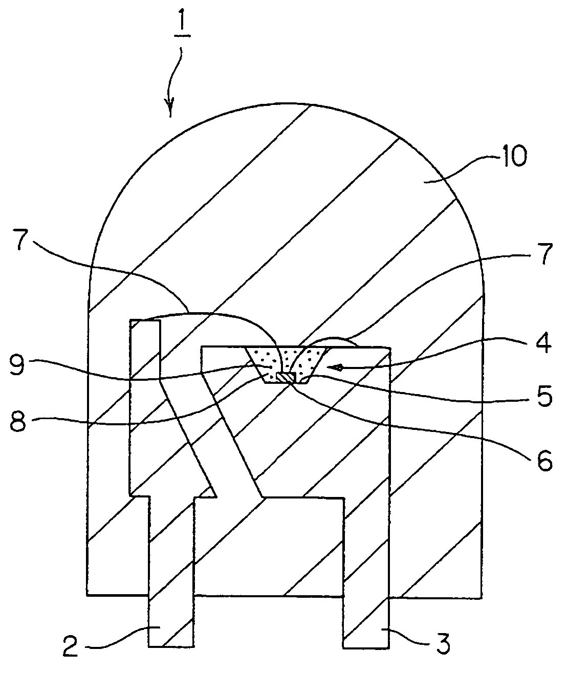
[0118]FIG. 4 is a cross-sectional view showing a light emitting device in the first embodiment of the invention.
[0119]This light emitting device 1 is a wavelength conversion-type light emitting device 1 comprising an LED element mounted on a lead. This device 1 includes leads 2 and 3 as wiring conductors. A cup part 4 for receiving an LED element is provided on the lead 2. An LED element 6 is bonded to the cup part 4 in its bottom part 5. The leads 2 and 3 are electrically connected to electrodes (not shown) of the EL element 6 through wires 7 of gold (Au). The cup part 4, together with the LED element 6 and the wire 7, is sealed with a light transparent sealing resin 8. A luminous body 9 is mixed in the sealing resin 8. The leads 2 and 3, the LED element 6, and the wires 7 are integrally sealed with a light transparent and shell-shaped sealing resin 10.
[0120]The leads 2 and 3 are formed of copper or a copper alloy having excellent thermal conductivity and electrical conductivity. T...
second embodiment
[0167]FIG. 7 shows a light emitting device in the second embodiment of the invention, wherein (a) is a longitudinal sectional view and (b) is a partially enlarged view of an LED element. Parts corresponding to the respective parts in the first embodiment are identified with the same reference numerals.
[0168]In this light emitting device 1, a flip chip-type LED element 11 is used as the light source. As shown in FIG. 7(a), the light emitting device 1 includes an LED element 11. A submount part 13 formed of Si is electrically connected through Au bumps 12A and 12B to the LED element 11. An Ag paste 14 as an electrically conductive adhesive electrically connects the submount part 13 to a lead 15A in its cup part 15a. A lead 15B is electrically connected to the submount part 13 through a wire. An element receiving part 15C is provided in the lead 15A. An inclined light reflective surface 15b is provided within the element receiving part 15C.
[0169]As shown in FIG. 7(b), the LED element 1...
third embodiment
[0175]FIG. 8 is a cross-sectional view showing a light emitting device in the third embodiment of the invention.
[0176]The construction of this light emitting device 1 is such that a cap-shaped luminous body layer 18 formed of a resin material such as an epoxy resin containing the luminous body 9 explained above in connection with the first and second embodiments is provided on the surface of the shell-shaped sealing resin 10, and the luminous body 9 has been omitted from the sealing resin 8 for sealing the cup part 15a.
[0177]The light emitting device 1 in the third embodiment is advantageous in that, in addition to the favorable effects of the first and second embodiments, an additional effect can be attained. Specifically, since the luminous body 9 is not deposited around the LED element 11, a lowering in efficiency of emission to the outside of the light emitting device caused by the absorption of light in the deposited phosphor can be prevented. By virtue of this effect, light e...
PUM
| Property | Measurement | Unit |
|---|---|---|
| wavelengths | aaaaa | aaaaa |
| color temperature | aaaaa | aaaaa |
| color wavelength | aaaaa | aaaaa |
Abstract
Description
Claims
Application Information
 - R&D
- Intellectual Property
- Life Sciences
- Materials
- Tech Scout
- Unparalleled Data Quality
- Higher Quality Content
- 60% Fewer Hallucinations
Browse by: Latest US Patents, China's latest patents, Technical Efficacy Thesaurus, Application Domain, Technology Topic, Popular Technical Reports.
© 2025 PatSnap. All rights reserved.Legal|Privacy policy|Modern Slavery Act Transparency Statement|Sitemap|About US| Contact US: help@patsnap.com


