Differential pressure type flowmeter and differential pressure type flow controller

a flowmeter and differential pressure technology, applied in non-electric variable control, process and machine control, instruments, etc., can solve problems such as difficulty in practical use, inability to achieve accurate practical etc., to achieve high accuracy, low cost, and high accuracy in flow rate measurements or flow rate control

Active Publication Date: 2008-05-06
FUJIKIN INC +1
View PDF13 Cites 9 Cited by
  • Summary
  • Abstract
  • Description
  • Claims
  • Application Information

AI Technical Summary

Benefits of technology

[0042]With the present invention, the structure of a differential pressure type flowmeter and the like is remarkably simplified, and it is so constituted that a flow rate computation is performed by using a novel empirical flow rate computation equation which makes it possible to obtain a computation flow rate value corresponding with the measured value with high accuracy, thus allowing the flowmeter and the like to be manufactured at low cost, and moreover, they take an inline form, and can be used without constraints of fitting positions, and a control flow rate is not influenced nearly at all by pressure changes, enabling highly accurate flow rate measurements or flow rate control in real time.
[0043]Also, with the present invention, it is so made that a control computation circuit is equipped with a correction data memory circuit for pressure changes, and a correction circuit for a computation flow rate, thus enabling easy correction even when pressure changes arise on the secondary side of an orifice. Therefore, highly accurate flow rate measurements or flow rate control can be achieved virtually without being influenced by pressure changes even a pressure P2 on the secondary side of an orifice is under a vacuum (a low pressure of less than 50 Torr).
[0044]Furthermore, with the present invention, it is so made that a differential pressure type flowmeter for a small flow quantity and a differential pressure type flowmeter for a large flow quantity are organically and integrally assembled. Therefore, highly accurate flow rate measurements with errors (% SP) of less than 1 (% SP) can be performed continuously over a wide flow rate range from the rated flow rate (100%) to a small flow quantity (1%) or approximately 1% of the rated flow rate, by both differential pressure type flowmeters being switched.
[0045]In addition, with the present invention, the control system can be further simplified by making the switching operation, for both differential pressure type flowmeter for a small quantity and differential pressure type flowmeter for a large quantity, automatic with a single-system control signal Sc.
[0046]As stated above, the present invention achieves excellent, practical effects that all types of gases are measured or controlled over the wide flow rate range with high accuracy even when a gas of less than 100 Torr is used although the differential pressure type flowmeter and the like are structured simply and at low cost.

Problems solved by technology

However, when a flow rate is in a small flow quantity range of less than approximately 10% of the maximum flow rate, problems that a practical flow rate measurements or flow rate control cannot be achieved with accuracy arise in reality.
Furthermore, with the improved pressure type flowmeter and the like, a measurement error (% SP or %FS) becomes comparatively larger to the reference set flow rate when a pressure P2 on the downstream side of an orifice becomes vacuum of less than approximately 200 Torr, thus resulting in occurrence of difficulties in practical use.

Method used


Image

  • Differential pressure type flowmeter and differential pressure type flow controller
  • Differential pressure type flowmeter and differential pressure type flow controller
  • Differential pressure type flowmeter and differential pressure type flow controller

Examples


first embodiment

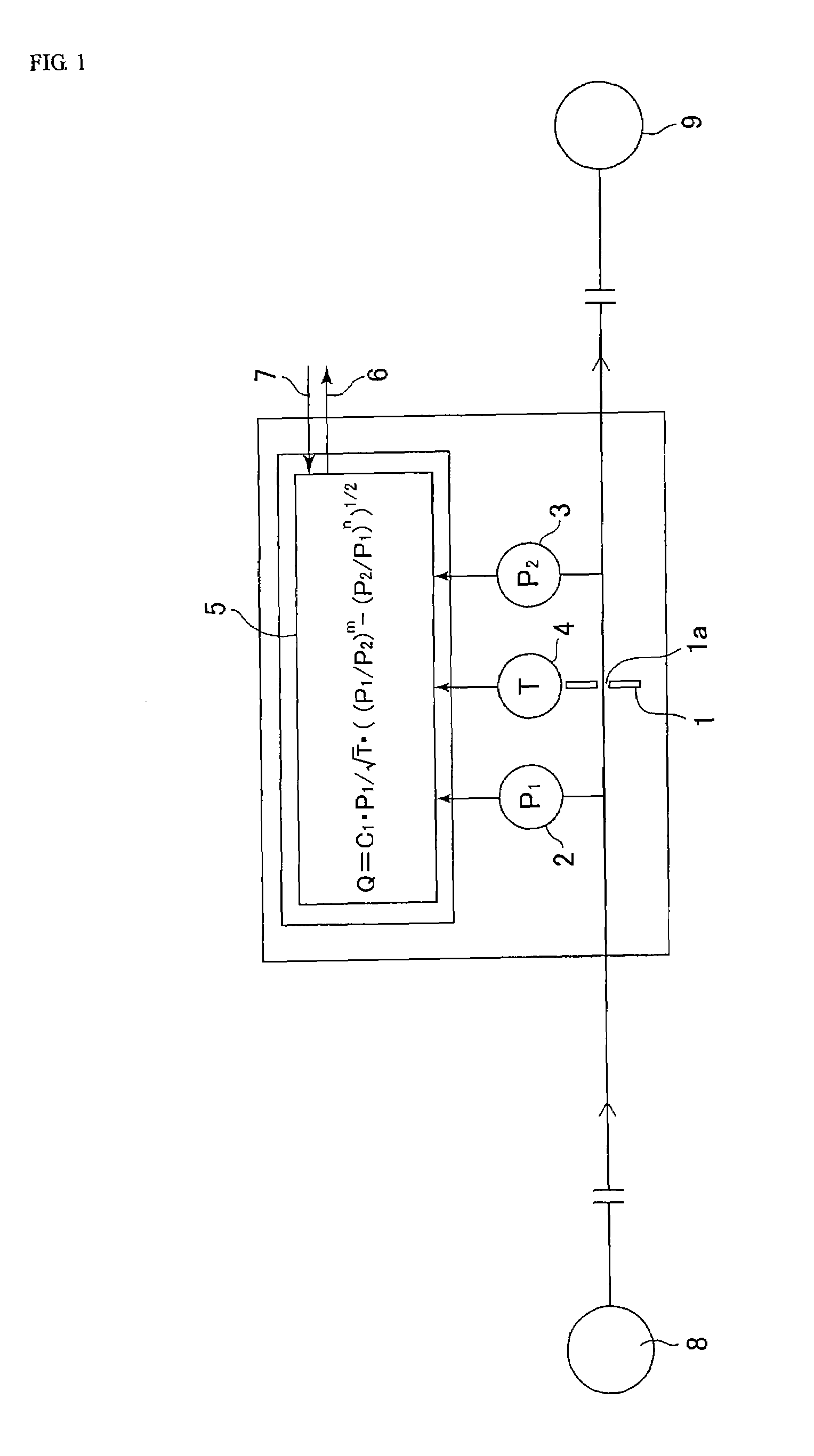
[0112]FIG. 1 is a basic block diagram of a differential pressure type flowmeter according to the present invention. The differential pressure type flowmeter comprises an orifice 1, an absolute pressure type pressure detector 2 on the upstream side of an orifice, an absolute pressure type pressure detector 3 on the downstream side of an orifice, a gas absolute temperature detector 4 on the upstream side of an orifice, a control computation circuit 5, an output terminal 6, an input terminal 7, and the like. And, 8 designates a gas supply facility and 9 a gas use facility (a chamber).

[0113]With the differential pressure type flowmeter according to the present invention, a gas flow rate Q passing through an orifice 1 under differential pressure conditions (that is, under non-critical conditions) is computed by an empirical flow rate equation as the below-stated equation (1), and the computed value is outputted to the outside through the output terminal 6.

Q=C1·P1 / ·T·((P2 / P1)m−(P2 / P1)n)1 / ...

third embodiment

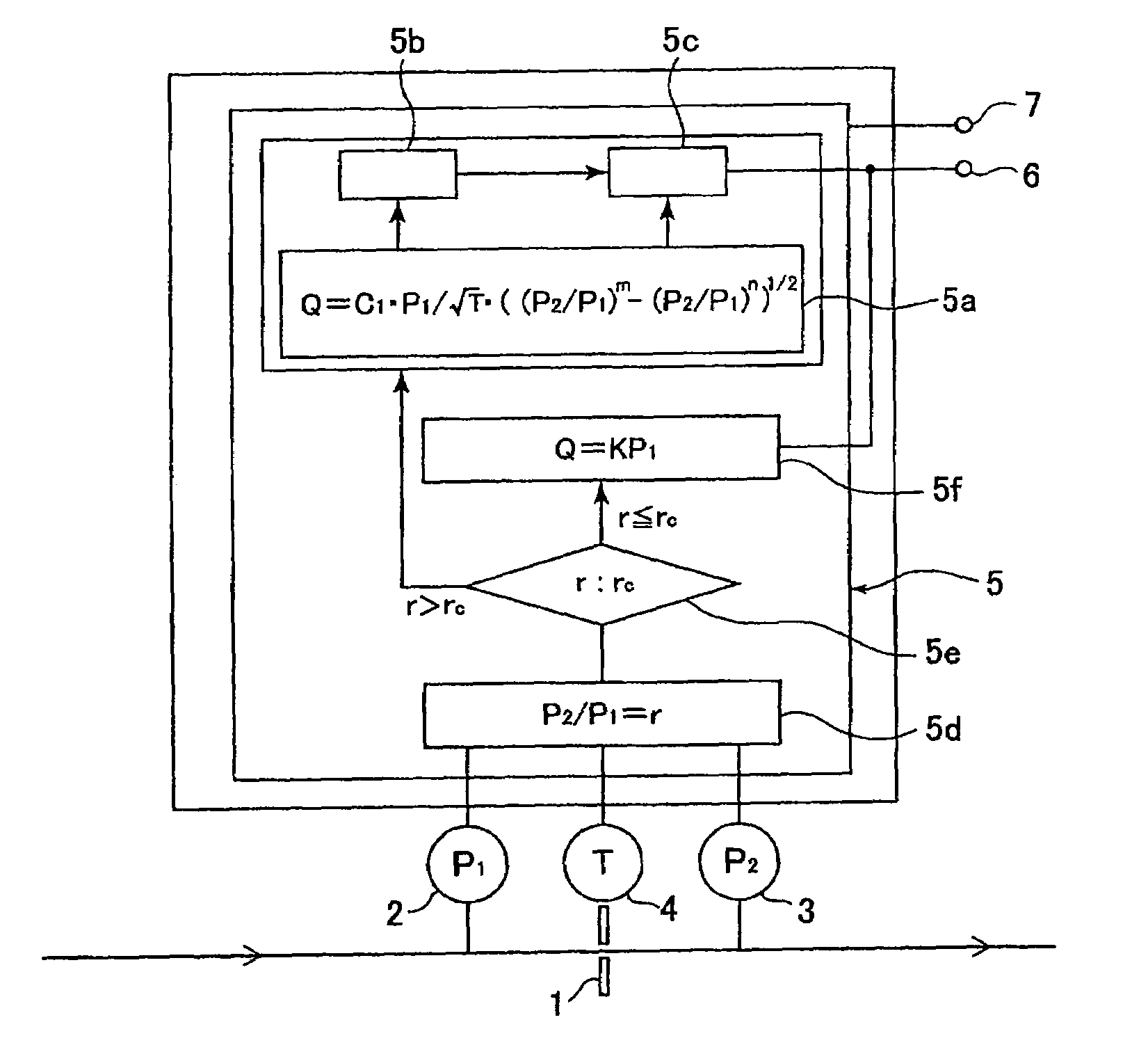
[0139]FIG. 6 illustrates the present invention. With a differential pressure type flowmeter in FIG. 5, it is so made that a flow rate equation Q=KP1 is used for computing a flow rate when it is under critical conditions, and a flow rate computation is performed with a control computation circuit 5 in FIG. 5 when it is under non-critical conditions.

[0140]Namely, as shown in FIG. 6, with a differential pressure type flowmeter in the third embodiment, a pressure ratio computation circuit 5d, a critical conditions judgment circuit 5e, and a flow rate computation circuit 5f for critical conditions are added to a control computation circuit 5 in FIG. 5. First, the ratio (γ) of a pressure P1 on the upstream side of an orifice versus a pressure P2 on the downstream side of an orifice is determined, and a pressure ratio (γ) and a critical pressure ration (γc) are compared. And, a flow rate computation is performed with the equation Q=KP1 when it is under critical conditions, to output the co...

fourth embodiment

[0143]FIG. 7 is a whole block diagram of a differential pressure type flowmeter according to the Referring to FIG. 7, 10 designates the No.1 switching valve (NC type), 11 the No.2 switching valve (NC type), a a gas inlet side, b a gas outlet side, 1′ the No.1 orifice (for a small quantity), 1″ the No.2 orifice (for a large quantity), 5′ the No.1 control computation circuit, and 5″ the No.2 control computation circuit.

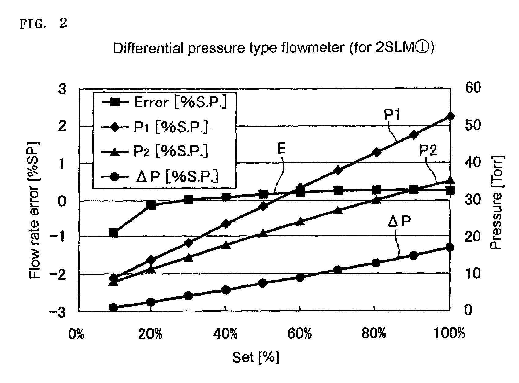
[0144]Namely, a differential pressure type flow controller for a small flow quantity side (i.e., a flow rate range of 10-100 sccm) is formed with the No.1 orifice 1, the No.1 computation circuit 5′ and the like, and a differential pressure type flow controller for a large flow quantity side (i.e., a flow rate range of 100-1000 sccm) is formed with the No.2 orifice 1′, the No.2 computation circuit 5″ and like. Therefore, highly accurate measurements of a flow rate can be achieved over the wide flow range of 1000 sccm(100%)-10 sccm (1%) with errors of less than 1 (% SP) ...


PUM


Abstract

A differential pressure type flowmeter comprises an orifice, a detector to detect a fluid pressure P1 on the upstream side of an orifice, a detector to detect a fluid pressure P2 on the downstream side of an orifice, a detector to detect a fluid temperature T on the upstream side of an orifice, and a control computation circuit to compute a fluid's flow rate Q passing through an orifice by using the pressure P1, where P2 and temperature T detected with the aforementioned detectors, and the aforementioned fluid's flow rate Q is computed with the equationQ=C1•P1 / √T•((P2 / P1)m−(P2 / P1)m)1 / 2 (where C1 is a proportional constant, and m and n are constants).

Description

[0001]This is a National Phase Application in the United States of International Patent Application No. PCT / JP2004 / 008596 filed Jun. 18, 2004, which claims priority on Japanese Patent Application No. 2003-190988, filed Jul. 3, 2003. The entire disclosures of the above patent applications are hereby incorporated by reference.FIELD OF THE INVENTION[0002]The present invention is concerned with improvements in or relating to a differential pressure type flowmeter and differential pressure type flow controller (together hereinafter called a differential pressure type flowmeter and the like) employed for semiconductor manufacturing facilities, at chemical plants, food-products processing plants and the like. The invention may be manufactured at a low cost and with a structural simplicity, and used in a state of so-called inline, and at the same time, make it possible that a flow rate of a fluid either under of criticality or non-criticality is measured or controlled with accuracy and in r...

Claims


Application Information

Patent Timeline
Patent Type & Authority Patents(United States)
IPC IPC(8): G01F1/37G01F1/00G01F1/42G01F1/50G01F1/88G01F7/00G05D7/06
CPCG01F1/42G01F1/50G05D7/0635G01F7/00
Inventor OHMISUGIYAMA, KAZUHIKOUNO, TOMIOIKEDA, NOBUKAZUNISHINO, KOUJINAKAMURA, OSAMUDOHI, RYOUSUKEMATSUMOTO, ATSUSHI
Owner FUJIKIN INC
Why Eureka
Try Eureka