
Hardfacing alloy, methods, and products

a technology of hardfacing alloy and hardfacing, applied in the field of hardfacing alloy, can solve the problems of tungsten carbide being expensive, the surface of tool joints and stabilizers is prone to wear, and the cost of tungsten carbide is high, so as to minimize the induced casing wear, maximize the resistance of the tool joint, and protect the effect of abrasion

Active Publication Date: 2008-04-22
ATT TECH LTD D B A ARNCO TECH TRUST +1
View PDF113 Cites 67 Cited by
  • Summary
  • Abstract
  • Description
  • Claims
  • Application Information

AI Technical Summary

Benefits of technology

"The present invention provides a hardfacing alloy that can be used for protecting wear prone surfaces of tool joints and stabilizers in industrial applications. The alloy has excellent abrasion resistance, low coefficient of friction, and can be deposited in single and double layers. It can be welded on various surfaces and can improve the service life of tool joints and stabilizers. The alloy can be used for hardbanding and can also be used on other industrial products that require abrasion resistance."

Problems solved by technology

There has been a severe problem with the service life of tool joints and stabilizers used in earth boring such as drilling a bore hole in the earth to a formation or formations from which oil or gas are to be produced since approximately 95 percent of the surface of the earth is composed of silicious materials which are very abrasive and which cause considerable wear on the surfaces of tool joints and stabilizers, as well as on wear prone surfaces of other industrial products.
Tungsten carbide is expensive, it acts as a cutting tool to cut the well casing in which it runs, and the matrix is a soft steel which erodes away easily to allow the carbide particles to fall away.
Most prior art hardfacing materials harder than silicious earth materials are brittle and crack in a brittle manner after solidification and upon cooling due to the brittle nature of its structure and the inability of the structure to withstand solidification shrinkage stresses and typically emit sound energy upon cracking as well as causing considerable casing wear as previously stated.
When the loss of human life may be involved or when great property damage may result, the requirements for integrity are particularly strict.
These primary carbides at this high hardness are brittle, have little tensile strength and hence pull apart on cooling from molten state at a frequency that depends on the relative quantity of the primary carbides in the mix of metal and carbide.
Thus, this type of hardfacing material, which is harder than silicious earth materials, when applied by welding or with bulk welding form shrinkage cracks across the weld bead.
Structures of this type are however affected by a high degree of brittleness and a high sensitivity to cracking when deposited by welding.
Hence they exhibit quite a high risk of spalling under actual service conditions.
In addition they are not characterized by particularly attractive or low friction coefficients.
These cases are however limited to low-alloyed carbon-steel weld metals in which boron is used often in conjunction with Titanium to promote the formation of a particular type of phase known as acicular ferrite.
Also, in high Carbon high alloyed Fe-based hardfacing weld metals, Boron has been used at levels of about up to 1 percent with the objective of strengthening the matrixes by induction of martensitic types of transformation, but in all cases at the expense of a significant increase of the brittleness of the alloys especially when boron additions are combined with high carbon contents.

Method used


Image

  • Hardfacing alloy, methods, and products
  • Hardfacing alloy, methods, and products
  • Hardfacing alloy, methods, and products

Examples


Embodiment Construction

[0044]The hardfacing composition of the present invention comprises by weight from about 0.45 to about 0.8 percent Carbon, about 3.5 to about 4.5 percent Boron, about 0.8 to about 1.25 percent Manganese, about 4.5 to about 6.5 percent Niobium, about 0.6 to about 0.8 silicon, about 2.0 to 2.5 percent Nickel, and the balance iron with impurities as trace elements.

[0045]The hardfacing alloy composition of the present invention has an all weld hardness of from about 63 Rc (772 Hv) to 66 Rc (865 Hv), an average hardness single layer on industrial products, such as tool joints and drill stabilizers of about 595 Hv, a quadratic crystallographic boride and eutectic structure, a balance of metal to metal and abrasion resistance, and is capable of being deposited in single and double layers on top of itself or on pre-existent hardband alloys, such as tungsten carbide deposits.

[0046]The hardfacing alloy composition is preferably deposited by metal cored tubular wire containing the hardfacing a...


PUM

PropertyMeasurementUnit
Brinell hardness numberaaaaaaaaaa
abrasion resistantaaaaaaaaaa
hardnessaaaaaaaaaa

Abstract

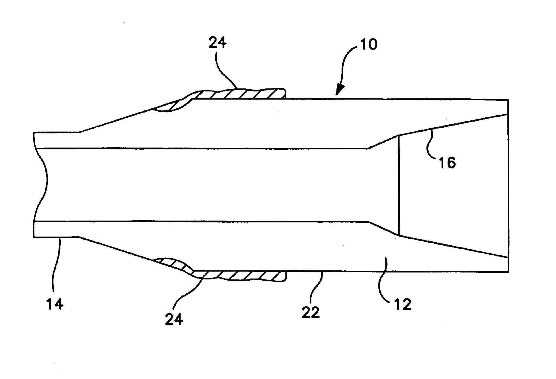
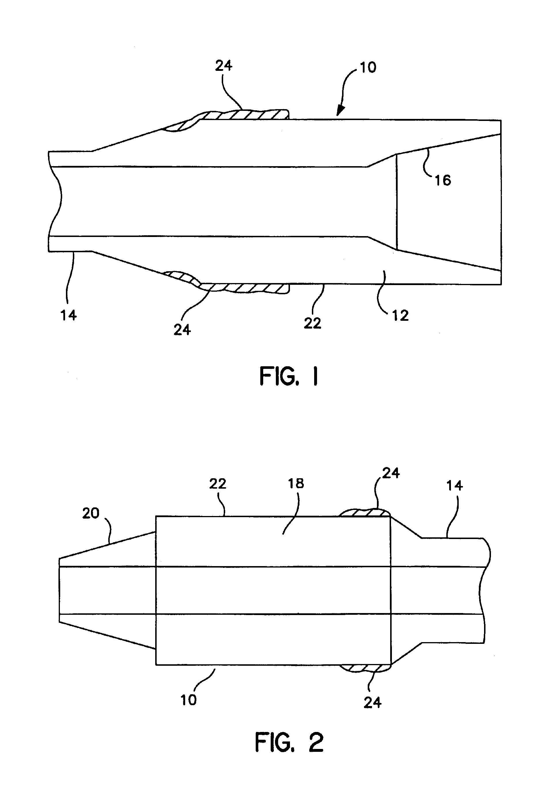
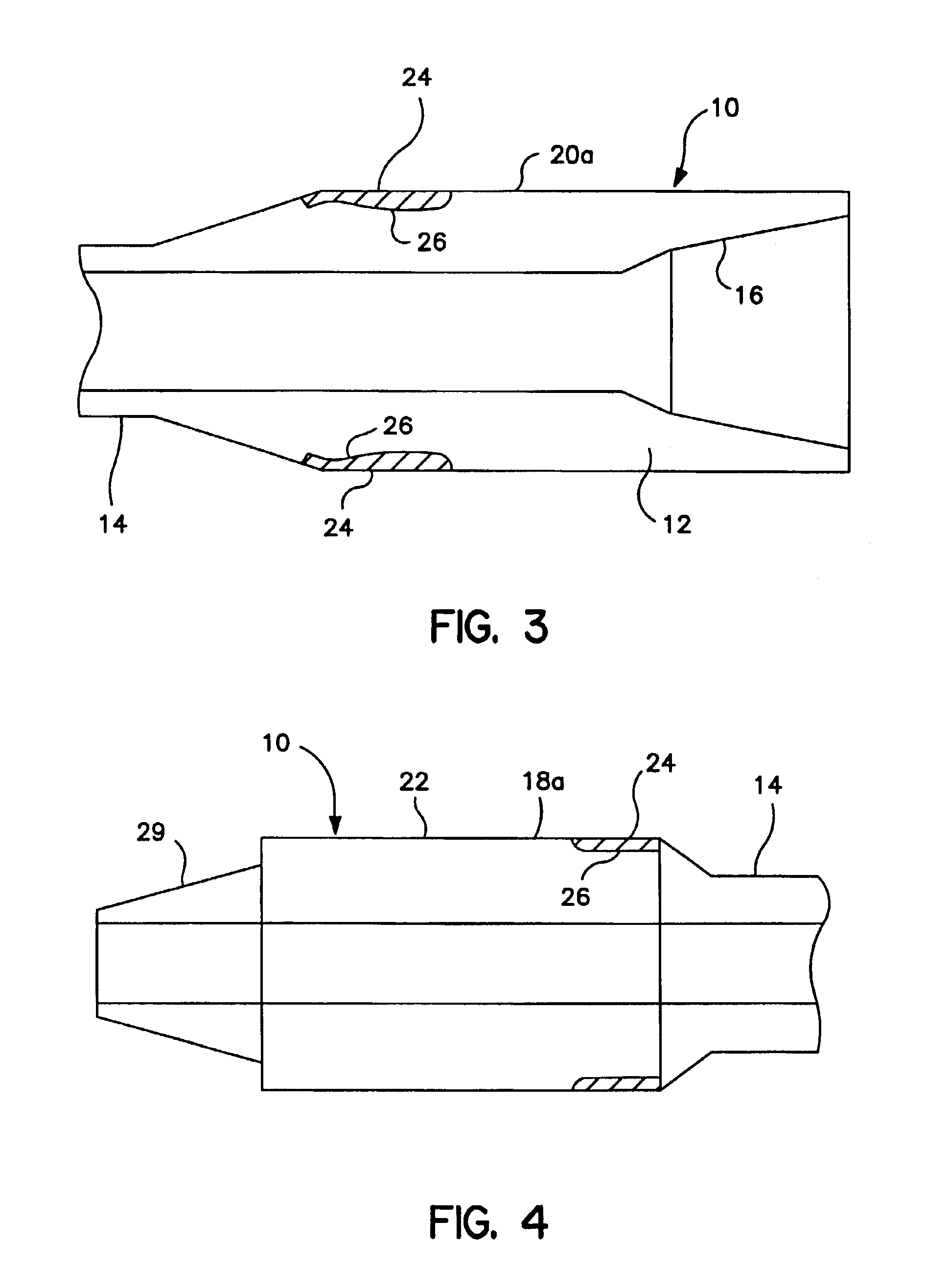
Disclosed is a hardfacing alloy capable of withstanding service abrasion of the order of silicious earth particles and weldable on industrial products, such as tool joints and stabilizers used in oil and gas well drilling, and other industrial products. The hardfacing alloy has a low coefficient of friction resulting from excellent metal to metal resistance and significant reduction in industrial wear on industrial products, such as casing wear. Other embodiments of the invention include tool joints having the hardbanding alloy welded to the outer cylindrical surface to its box and pin members and to stabilizer ribs on the stabilizer used in earth boring, such as boring for oil and gas, other industrial products, and methods of applying the hardfacing alloy to their surfaces. The hardfacing alloy does not require any post weld treatment, has primary borides in its microstructure, the carbons in the alloy are tied up in the formation of secondary carbides which add to the abrasion resistance, and have a quadratic crystallographic structure and a hardness of about 1725 Hv comparable to the prior art hardness of the chromium carbide primary carbide alloys of the prior art but is substantially less brittle than C—Cr—Fe hardfacing alloys.

Description

FIELD OF THE INVENTION[0001]The present invention is in the field of hardfacing alloys having high abrasion resistance for improving the service life of surfaces of industrial products subject to wear such as tool joints, drill collars, and stabilizers used in drilling strings for earth boring for oil and gas as well as other industrial products subjected to high abrasion.BACKGROUND OF THE INVENTION[0002]There has been a severe problem with the service life of tool joints and stabilizers used in earth boring such as drilling a bore hole in the earth to a formation or formations from which oil or gas are to be produced since approximately 95 percent of the surface of the earth is composed of silicious materials which are very abrasive and which cause considerable wear on the surfaces of tool joints and stabilizers, as well as on wear prone surfaces of other industrial products.[0003]There have been numerous attempts to provide hardfacing alloys suitable for welding protective hardfac...

Claims


Application Information

Patent Timeline
Patent Type & Authority Patents(United States)
IPC IPC(8): B32B15/01B23K35/22B32B15/16C22C38/02C22C38/04C22C38/08C22C38/12B23K9/04B23K35/30B23K101/20B32B15/18E21B17/10F16L58/08F16L58/18
CPCB23K9/04B23K35/3093C22C38/002C22C38/02C22C38/04C22C38/08C22C38/12E21B17/1085F16L58/08F16L58/182B23K9/046Y10T428/12972B23K2201/002Y10T428/12576Y10T428/12861Y10T428/12771Y10T428/12396Y10T428/12806B23K2101/002
Inventor DAEMEN, ROGER AUGUSTEMOLINE, KEITH E.
Owner ATT TECH LTD D B A ARNCO TECH TRUST
Learn More