
Anode-supported flat-tubular solid oxide fuel cell stack and fabrication method of the same

a technology of solid oxide fuel cell and anode support, which is applied in the direction of fuel cell details, final product manufacturing, climate sustainability, etc., can solve the problems of increasing the production cost of fuel cells, low power density, and increasing the production cost of tube-type solid oxide fuel cells, so as to improve the power density. a relatively low

Inactive Publication Date: 2007-10-23
TRUE DIGITAL LEADER CO LTD
View PDF8 Cites 3 Cited by
  • Summary
  • Abstract
  • Description
  • Claims
  • Application Information

AI Technical Summary

Benefits of technology

"The present invention provides an anode-supported flat-tubular solid oxide fuel cell stack that includes an anode-supported tube with semi-cylinder parts and plate parts. This design improves the power density of the fuel cell stack while still utilizing its advantages. The method of fabricating this fuel cell stack is also provided."

Problems solved by technology

The plate type solid oxide fuel cell has a higher current density than a disk type fuel cell, but has disadvantages in that a large-sized plate type fuel cell necessarily needed to produce a large capacity fuel cell is difficult to produce using the plate type solid oxide fuel cell due to several problems, such as sealing gas and thermal shock due to a difference of thermal equilibrium coefficient between constituents of the fuel cell.
However, the tube type solid oxide fuel cell has disadvantages in that the tube type solid oxide fuel cell has a lower power density per unit area than the plate type solid oxide fuel cell, and the production costs of the tube type solid oxide fuel cell are relatively high.
Meanwhile, a conventional tube type fuel cell is an air electrode-supported fuel cell using an air electrode as the support of the fuel cell, and the production costs of the fuel cell are increased because raw materials for the air electrode such as La and Mn, are very expensive, and production of LSM (LaSrMnO3) is difficult.
In addition, the unit cell is low in mechanical strength and does not withstand impact because the air electrode acting as the support is made of ceramics while an anode is made of cermet consisting of metals and ceramics.
Furthermore, an electrolyte layer is coated on a surface of the air electrode-supported tube according to a process requiring high coating costs during fabrication of the conventional air electrode-supported tubular solid oxide fuel cell, thus the conventional air electrode-supported tubular solid oxide fuel cell is disadvantageous in terms of economic efficiency.
In other words, the air electrode is fragile because the air electrode is made of high-priced ceramics, such as La, which is used as the support in the conventional air electrode-supported tubular solid oxide fuel cell, the strength of the air electrode is reduced due to a chemical reaction, in the ceramic structure constituting the air electrode, at high temperatures, and the fuel cell price is increased because the electrolyte layer is formed on the surface of the air electrode by use of the very costly EVD process.
The anode-supported tubular solid oxide fuel cell has a disadvantage in that the very thin and dense electrolyte layer should be formed on the surface of the porous anode-supported tube with a wide surface area.
When the electrolyte layer is formed by a physical and chemical vapor deposition process using a vacuum such as an EVD process or a plasma spray coating process, a dense and thin electrolyte layer can be formed, but equipment used to form the electrolyte layer is undesirably large and the reaction time is excessively long.
In addition, the above processes are not suitable to produce the fuel cell in commercial quantities because a few of the unit cell are deposited by the electrolyte at one time.

Method used

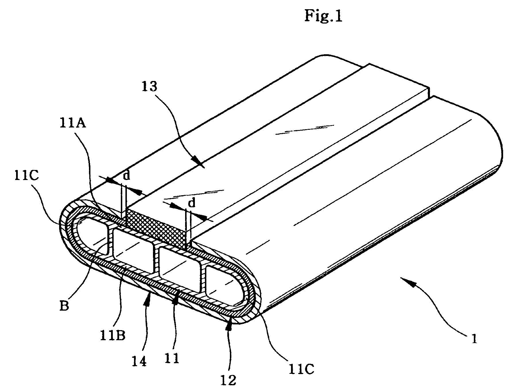

Image

  • Anode-supported flat-tubular solid oxide fuel cell stack and fabrication method of the same
  • Anode-supported flat-tubular solid oxide fuel cell stack and fabrication method of the same
  • Anode-supported flat-tubular solid oxide fuel cell stack and fabrication method of the same

Examples


Embodiment Construction

[0035]Reference will now be made in detail to the present preferred embodiments of the present invention, examples of which are illustrated in the accompanying drawings, wherein like reference numerals refer to like elements throughout.

[0036]An anode-supported flat-tubular solid oxide fuel cell stack according to the present invention is characterized in that it is provided with two or more fuel cells and three or more connector plates for desirably arranging the fuel cells and electrically connecting the fuel cells to each other. Additionally, the stack has the flat-tubular fuel cells to secure advantages of a plate-type and a tube-type fuel cell. Further, a connector is coated on an external surface of an supported tube according to a wet process such as a plasma spray coating process, or a slurry coating process to electrically connect the fuel cells to the connector plates.

[0037]A flat-tubular unit fuel cell constituting the stack according to the present invention includes semi...


PUM

PropertyMeasurementUnit
weightaaaaaaaaaa
temperatureaaaaaaaaaa

Abstract

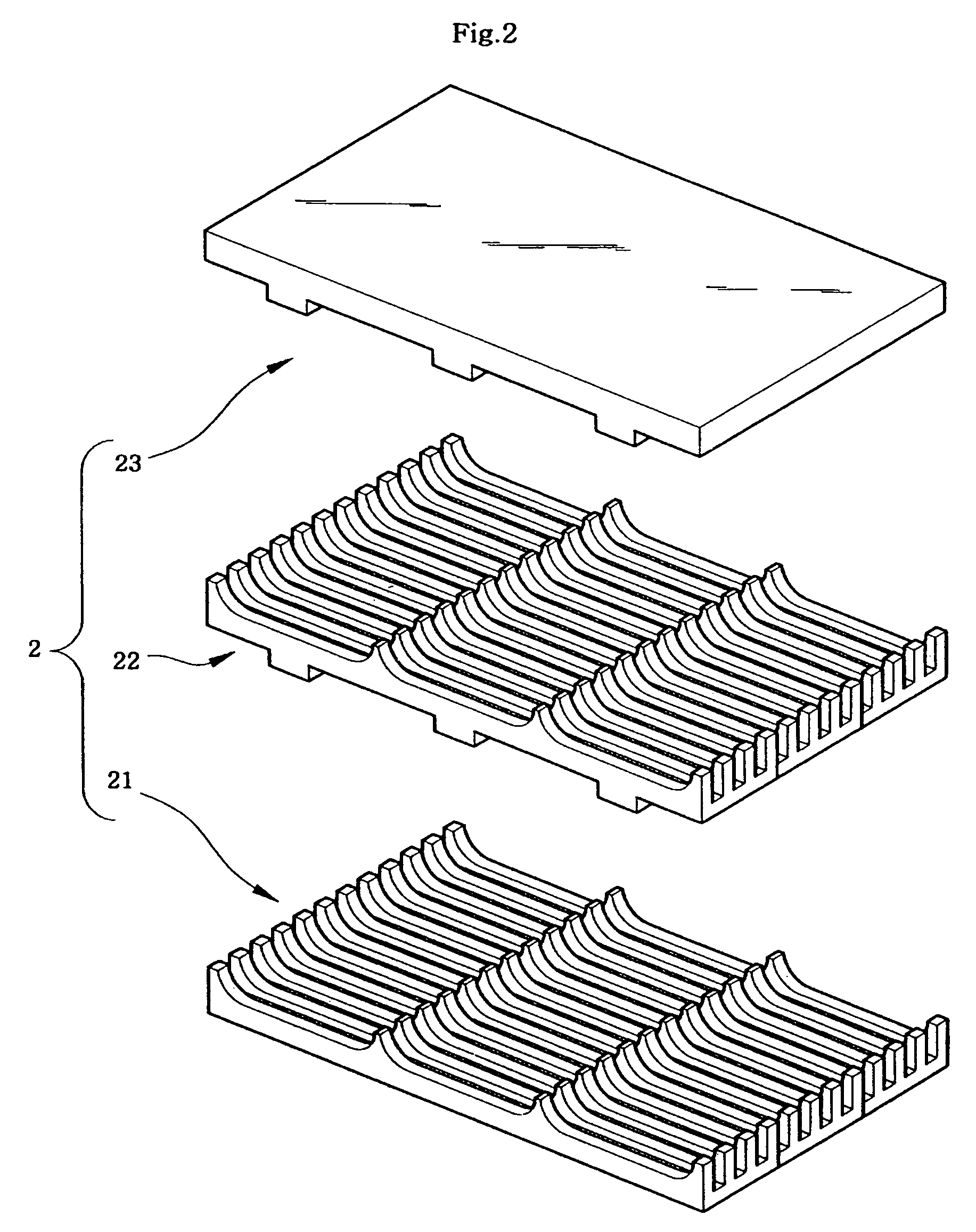
An anode-supported flat-tubular solid oxide fuel cell stack includes a plurality of fuel cells and a plurality of connector plates. Each of the fuel cells includes a supported tube having semi-cylinder parts and plate parts, a connector coated on an upper plate of the supported tube as a way to be positioned at the center of the upper plate, an electrolyte layer partly coated on an external surface of the supported tube except for a portion of the supported tube coming into contact with the connector, and an air electrode coated on an external surface of the electrolyte layer. Each of the connector plates includes a lower connector plate, middle connector plates, and an upper connector plate. A plurality of gas channels are formed on the middle and lower connector plates. The anode-supported flat-tubular solid oxide fuel cell stack has a large capacity, improved power density, and reduced production costs.

Description

BACKGROUND OF THE INVENTION[0001]1. Field of the Invention[0002]The present invention pertains to a flat-tubular solid oxide fuel cell stack using an anode as a supported body and a method of fabricating the stack. More particularly, the present invention relates to an anode-supported flat-tubular solid oxide fuel cell stack, which includes an anode-supported tube having semi-cylinder parts and plate parts, thereby having a combined structure of a tube-type and a plate-type anode-supported body, and a method of fabricating the stack. The anode-supported flat-tubular solid oxide fuel cell stack is advantageous in that fuel cells constituting the stack are easily sealed, and have excellent resistance to heat stress and improved power density per unit area.[0003]2. Description of the Related Art[0004]A fuel cell is a highly efficiency clean generator, in which hydrogen contained in a hydrocarbon based material such as natural gas, coal gas, or methanol, is electrochemically reacted wit...

Claims


Application Information

Patent Timeline
Patent Type & Authority Patents(United States)
IPC IPC(8): H01M8/10B05D5/12C04B35/01C04B35/26C04B35/42C04B35/64C04B38/06H01M4/88H01M4/90H01M8/02H01M8/12H01M8/24
CPCC04B35/016C04B35/2633H01M8/243C04B35/42C04B35/6263C04B35/6264C04B35/62655C04B35/6267C04B38/068H01M4/8885H01M4/9016H01M4/9033H01M4/9066H01M8/0217H01M8/0247H01M8/1253C04B35/48C04B38/0054C04B38/0074Y02E60/525Y02E60/521C04B2111/00853C04B2235/3208C04B2235/3213C04B2235/3227C04B2235/3246C04B2235/3275C04B2235/449C04B2235/5436C04B2235/656C04B2235/6584C04B2235/77C04B2235/80C04B2235/96Y02E60/50Y02P70/50H01M8/2404H01M8/2428
Inventor SONG, RAK-HYUNSHIN, DONG-RYULKIM, JONG-HEE
Owner TRUE DIGITAL LEADER CO LTD
Learn More