
Ink jet head and recording apparatus using the same

Inactive Publication Date: 2007-10-02
FUJIFILM HLDG CORP +1
View PDF26 Cites 5 Cited by
  • Summary
  • Abstract
  • Description
  • Claims
  • Application Information

AI Technical Summary

Benefits of technology

[0024]The present invention has been made in order to solve the above-mentioned problems inherent in the prior art, and has a first object to provide an ink jet head capable of achieving an ejection voltage reduction, widening a selection range for ink guide materials (low dielectric constant material becomes usable, for instance), and widening a selection range for ink guide tip end structures.
[0025]It is a second object of the present invention to provide a safe, low-cost, and widely applicable electrostatic ink jet recording apparatus and recording method that are capable of recording an image on a recording medium with stability by using the ink jet head described above which achieves the first object of the present invention.
[0026]It is a third object of the present invention to solve the above-mentioned problems inherent in the prior art by providing an ink jet head that is capable of achieving energy saving by reducing an ejection force required to supply ink to an ejection portion and to eject the ink from the ejection portion, shortening a delay time from exertion of an ejection force to ejection of an ink droplet having a correct size, preserving an ink meniscus with stability, and performing precise image recording through stabilized ink ejection, as well as a recording apparatus and a recording method using the ink jet head.
[0043]It is preferable that the ink jet head further comprises: a floating conduction plate that is provided to be common with respect to all (plural) ejection electrodes, and arranged closer to a side of the head substrate than the ink flow path. It is preferable that the ink jet head further comprises: a guard electrode which is provided between adjacent ejection electrodes and suppresses electric field interferences occurring between the adjacent ejection electrodes. It is preferable that the ink jet head further comprises: a shield electrode that is provided to be common with respect to all (plural) ejection electrodes, and arranged closer to a side of the ink flow path than the ejection electrode.

Problems solved by technology

The pulse voltage sources use a high voltage (around 400 to 600 V, for instance), so that when the individual electrodes and the pulse voltage sources are arranged at a high density, there involves a high risk of causing the discharge.
Accordingly, it is extremely difficult to cope with both high-density implementation and high-voltage driving.
However, if high pulse voltages are generated by the pulse voltage sources, current consumption is increased.
Also, the pulse voltage sources consume currents in order to generate the pulse voltages, so that if high pulse voltages are generated, the current consumption is increased.
However, when a large number of individual electrodes are used as described above, the increased current consumption causes a problem.
Consequently, there arises a problem in that loads on an electric circuit and the like are increased and operation stability is lowered.
Also, at the time of activation of the apparatuses (at the time of start of recording), a long time is taken to supply the ink to the ejection port, so that a delay time from exertion of an ejection force to actual ejection is elongated, during which it is impossible to eject an ink droplet having a predetermined size set for the ejection force.
Consequently, there involves a problem in that the dot sizes of first several dots become small and a print failure occurs.
Further, in JP 1-222970 A, the ink guide is made ink-receptive in order to enhance a contact property of the ink to the ink guide, which causes a problem in that the larger ejection force is necessary for ink ejection.

Method used


Image

  • Ink jet head and recording apparatus using the same
  • Ink jet head and recording apparatus using the same
  • Ink jet head and recording apparatus using the same

Examples


Embodiment Construction

[0090]An ink jet head according to the present invention, and a recording apparatus and a recording method using the ink jet head will now be described in detail based on preferred embodiments with reference to the accompanying drawings.

[0091]First, an electrostatic ink jet head according to first and second aspects of the present invention, an electrostatic ink jet recording apparatus according to a third aspect, and an electrostatic ink jet recording method according to a fourth aspect will be described with reference to FIGS. 1 to 15.

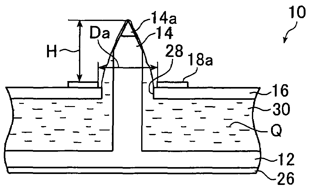
[0092]FIG. 1 is a schematic cross-sectional view showing an outlined construction of an embodiment of the ink jet head according to the first and second aspects of the present invention.

[0093]An ink jet head 10 shown in FIG. 1 is an electrostatic ink jet head and used for recording an image on a recording medium P in accordance with image data by ejecting ink Q containing charged fine particle component like pigments (toner, for instance) by means of...


PUM


Abstract

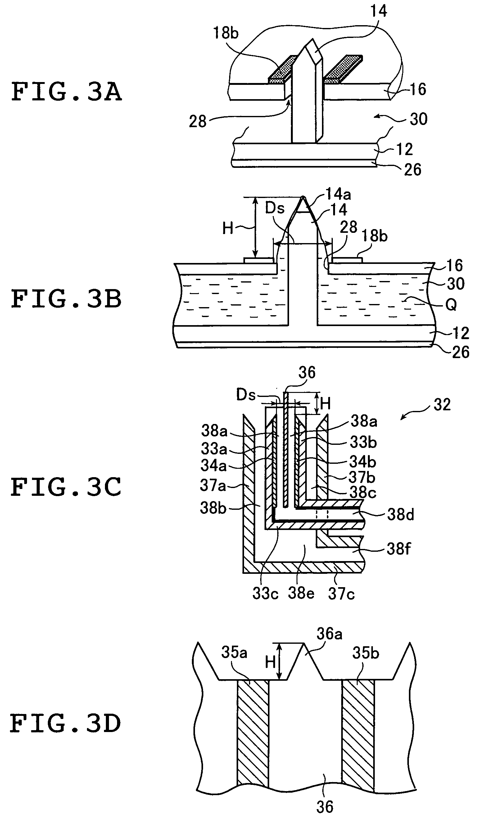
The ink jet head records an image on a recording medium by ejecting ink containing charged fine particles by means of an electrostatic force, and includes an ink guide, an ink flow path that supplies the ink to the ink guide and an ejection electrode that ejects the supplied ink. The ejection electrode includes a surrounding electrode arranged so as to surround an outer periphery of the ink guide with a spacing, or side-by-side electrodes arranged on both sides of the ink guide so as to oppose each other with a spacing. A ratio between an effective inside diameter of the surrounding electrode or an effective spacing between the side-by-side electrodes, and a distance from the surrounding electrode or the side-by-side electrodes to a tip end of the ink guide protruding on the side of the recording medium is set in a range of 1:0.5 to 1:2 or 1:0.7 to 1:2.8, respectively.

Description

BACKGROUND OF THE INVENTION[0001]1. Field of the Invention[0002]The present invention relates to an ink jet head that ejects ink as ink droplets, and a recording apparatus and a recording method using the ink jet head. More specifically, the present invention relates to an electrostatic ink jet head that controls ejection of ink containing charged fine particles by means of an electrostatic force, an ink jet head where energy required for ink ejection is reduced, and to a recording apparatus and a recording method with which an image is recorded on a recording medium using the ink jet head.[0003]2. Description of the Related Art[0004]An ink jet recording apparatus records an image on a recording medium by ejecting ink containing a colorant from ejection ports as ink droplets, which then fly and impinge on the recording medium. According to an ink droplet ejection method, there are known the ink jet recording apparatuses of an electrostatic system, a bubble system, a thermal system, ...

Claims


Application Information

Patent Timeline
IPC IPC(8): B41J2/06
CPCB41J2/06B41J2002/061
Inventor FURUKAWA, KOJI
Owner FUJIFILM HLDG CORP
Learn More