
Decoding method and apparatus

a modulated information and demodulation technology, applied in the field of decoding modulated information, can solve the problems of demodulation processing, reception errors, and 802.11b remains susceptible to multipath interference, and achieve the effect of improving isi and ici cancellation in reception

Active Publication Date: 2007-08-28
NXP USA INC
View PDF18 Cites 78 Cited by
  • Summary
  • Abstract
  • Description
  • Claims
  • Application Information

AI Technical Summary

Benefits of technology

[0008]Another aspect of present invention seeks to improve reception performance when symbols encoded by different modulation schemes are encountered, such as that specified for the high rate physical layer of the IEEE 802.11b standard. Yet another aspect is directed in particular to feedback equalization for Barker encoded symbols present in the received signal.

Problems solved by technology

Nevertheless, the confluence of strict power limits specified for operation in the 2.4 GHz ISM band and megabit+ expected data throughput rates limits conventional 802.11b to just a 100 or so feet between stations, depending on the number of interposing radio obstructions and reflections.
Thus 802.11b remains susceptible to multipath interference, and to reception errors produced by inter-symbol (“ISI”) and inter-chip interference (“ICI”) in particular.
However, these techniques appear to employ demodulation processing gain only after all chips of the preceding symbol have been received and correlated.
Further, these techniques do not exploit non-CCK modulated information contained within the received signal, such as the PLCP header and / or preamble, for equalization purposes.

Method used


Image

  • Decoding method and apparatus
  • Decoding method and apparatus
  • Decoding method and apparatus

Examples


Embodiment Construction

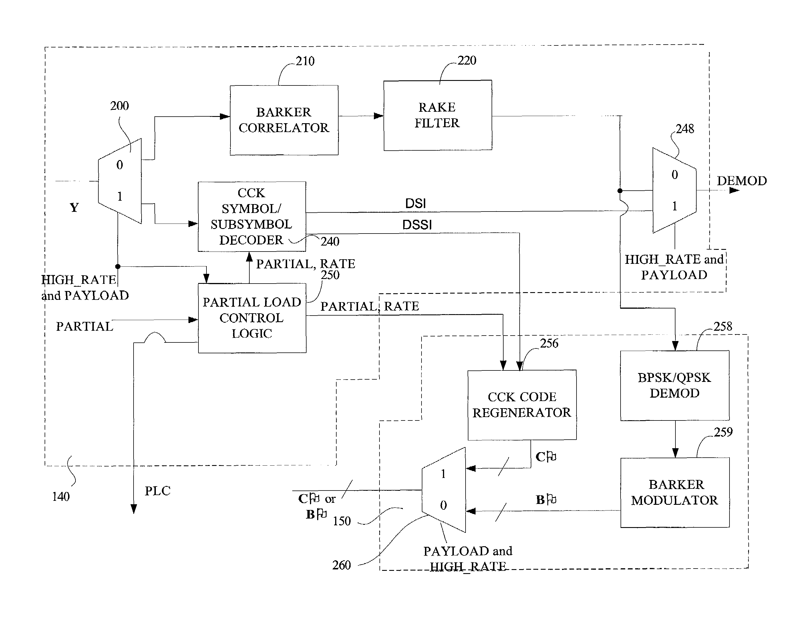
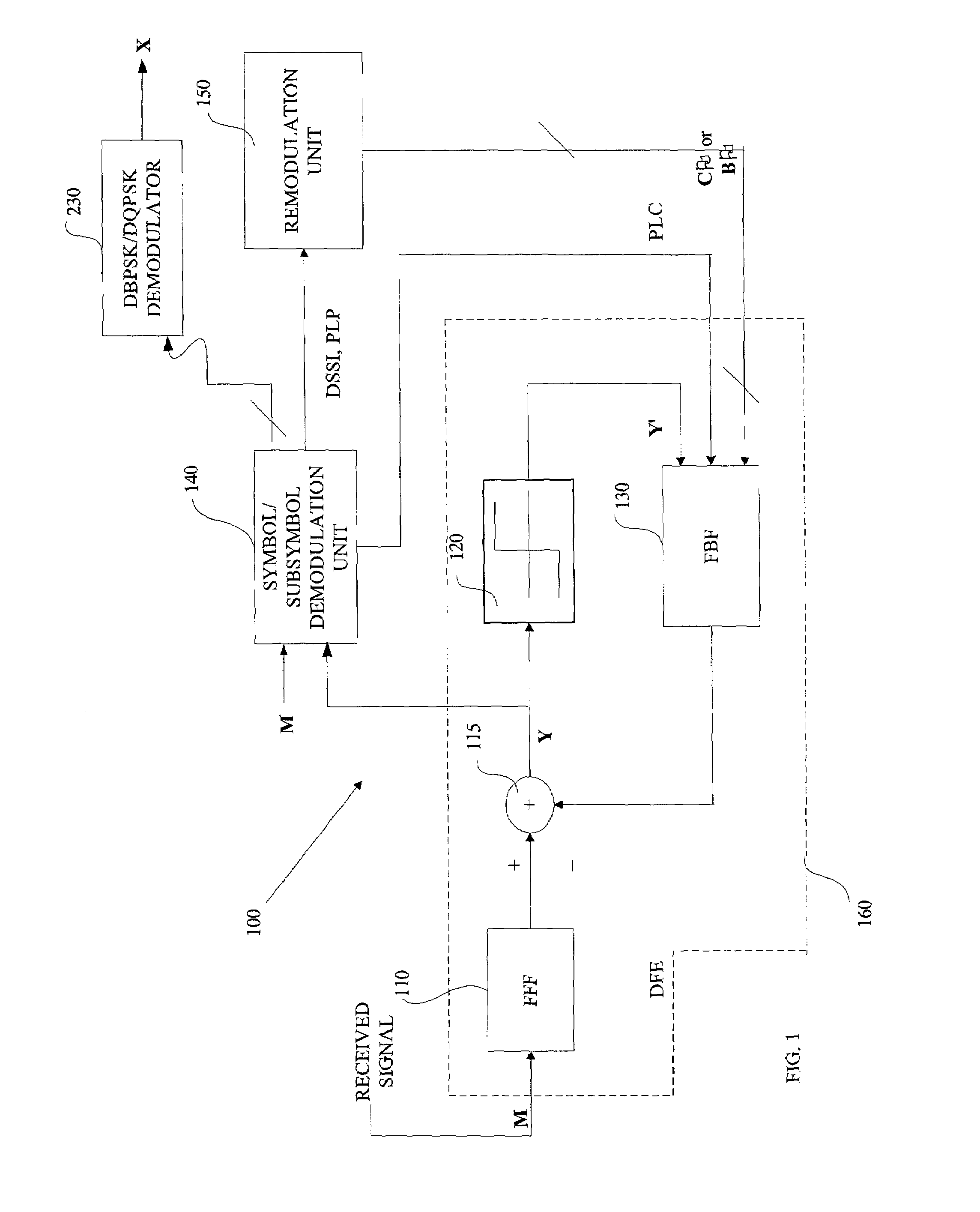
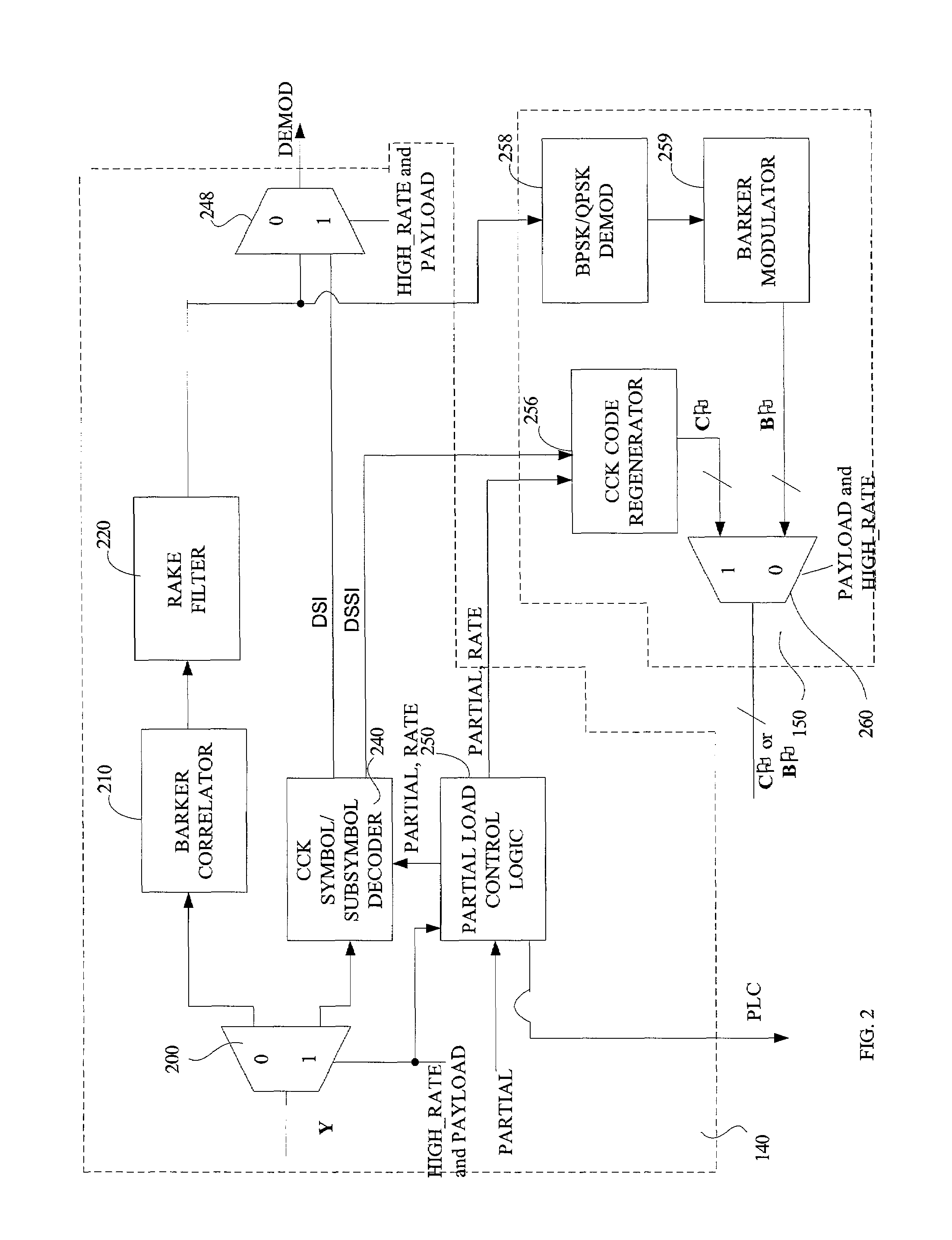
[0019]Turning first to FIG. 1, FIG. 1 is a high-level block diagram of a decoding unit 100 including a decision feedback equalizer (“DFE”) 160, symbol / subsymbol demodulation unit 140 and remodulation unit 150 in accordance with a first embodiment of the invention. One purpose of this decoding unit 100 is to decode a signal incorporating one or more modulated coded symbols representing data. Consistent with this purpose, feed forward processing is employed to help ensure that a received, coded symbol modulated baseband signal possesses the minimum phase characteristics to permit symbol demodulation. In turn, decision feedback analysis complemented with selective subsymbol and / or symbol decoding is employed to mitigate inter-symbol and inter-chip interference produced at least in part by the noise enhancing effects of such feed forward processing and thus achieve equalization. This leads to improved receiver performance in noisy environments, especially where multipath interference su...


PUM


Abstract

Techniques and instrumentalities to improve ISI and ICI cancellation in reception of modulated symbols by selectively decoding subsymbols of such modulated symbol before they can be completely decided or perceived as well as use of decoded symbol / subsymbol information in the feedback equalization process are disclosed. In particular, a decoder and corresponding method are disclosed which includes a feedback equalizer capable of receiving a modulated signal including a symbol defined by a first number of chips, along with a subsymbol processor to generate a subsymbol waveform upon receipt of a second number, less than the first number, of chips of such symbol and provide the subsymbol waveform to the feedback equalizer in order to equalize the modulated signal using the subsymbol waveform. Other disclosed aspects including techniques and instrumentalities for improving reception performance when symbols encoded by different modulation schemes are encountered, as well as feedback equalization for Barker encoded symbols present in the received signal.

Description

RELATED APPLICATION[0001]This application claims priority benefit under 35 U.S.C. § 119(e) (1) to U.S. Provisional Application No. 60 / 334,347, filed Nov. 29, 2001, entitled Method and Apparatus For Determining Signal Quality, which is incorporated herein fully by reference.TECHNICAL FIELD[0002]This invention is directed to decoding modulated information, and is particularly concerned with improved equalization techniques for useful in decoding such information.BACKGROUND[0003]The past few years has witnessed the ever-increasing availability of relatively cheap, low power wireless data communication services, networks and devices, promising near wire speed transmission and reliability. One technology in particular, described in the IEEE Standard 802.11b-1999 Supplement to the ANSI / IEEE Standard 802.11, 1999 edition, collectively incorporated herein fully by reference, and more commonly referred to as “802.11b” or “WiFi”, has become the darling of the information technology industry a...

Claims


Application Information

Patent Timeline
Patent Type & Authority Patents(United States)
IPC IPC(8): H04B1/69H04B1/713
CPCH04L25/03057H04L2025/03401H04L2025/0349
Inventor HSU, YUNGPINGXU, NELSONCHEUNG, RICKY
Owner NXP USA INC
Learn More