Method and apparatus for delayed recursion decoder

a delay decoder and recursion technology, applied in the field of signal processing devices and methods, can solve the problems of increasing the size, complexity and cost of the decoder, imposing an even greater decoding delay, and long critical path, so as to increase parallelization, accelerate clock rate, and increase the rate

Inactive Publication Date: 2007-04-17
II VI DELAWARE INC
View PDF10 Cites 73 Cited by
  • Summary
  • Abstract
  • Description
  • Claims
  • Application Information

AI Technical Summary

Benefits of technology

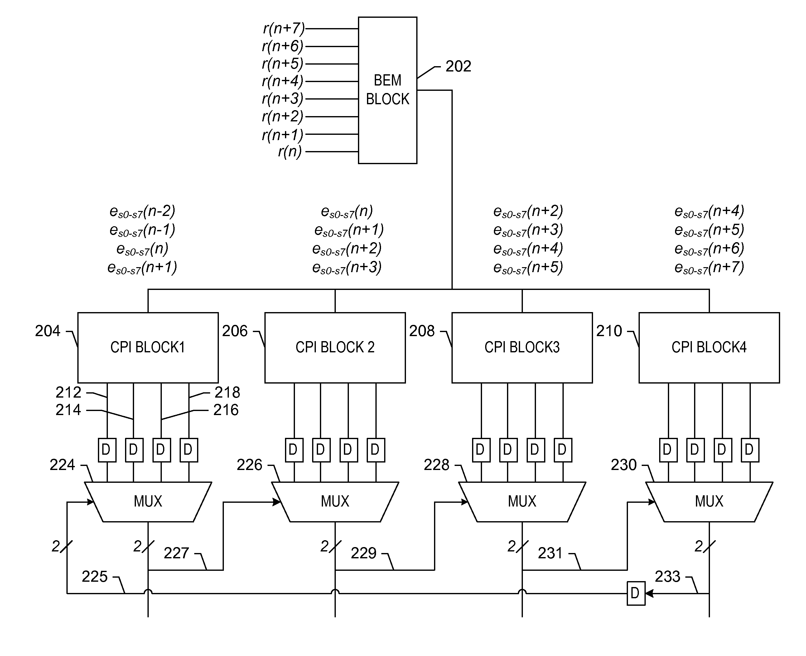
[0021]In a preferred embodiment, cumulative path metrics at the first stage of each decoder are not used. Rather, the path metric at each state or group of states is assumed to be zero, and candidate paths are determined from each such possible prior state or group of states. Then, prior decisions are used (instead of cumulative prior path metrics) to select the appropriate candidate path. This method has the advantage of allowing the recursion step, where the state decisions are fed forward to the next stage and are used to identify the appropriate candidate path (and corresponding decision bits),

Problems solved by technology

One significant disadvantage of the existing parallel Viterbi structures is that the parallel structure still provides a trellis that must be navigated using the add-compare-select process at each clock cycle.
Even though the clock rate of the collapsed-trellis decoder may be reduced by using parallel circuits to collapse the trellis, numerous add-compare-select operations may still have to be performed, resulting in a long critical path.
This of course increases the size, complexity and cost of the decoder and imposes an even greater decoding delay, which may be unacceptable.
Even in a highly parallel structure, the duration of the critical path may be such that the decoder circuit is incapable of operating at very high signal processing rates.
The signal link from the transmitter to the receiver is not ideal, especially at high data rates; several impairments degrade the quality of the signal as it traverses the li

Method used


Image

  • Method and apparatus for delayed recursion decoder
  • Method and apparatus for delayed recursion decoder
  • Method and apparatus for delayed recursion decoder

Examples


Embodiment Construction

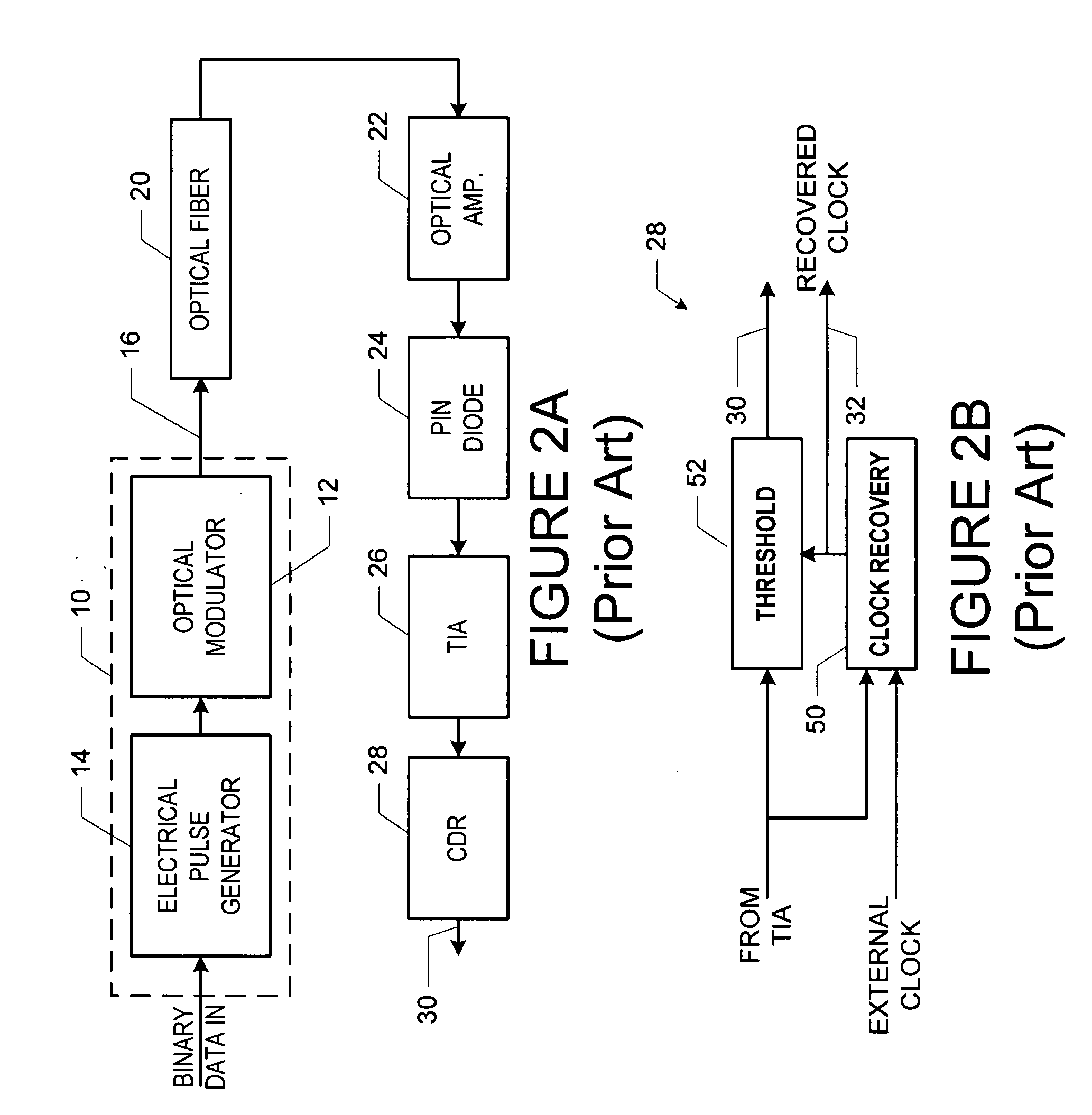
[0045]A preferred embodiment of the decoder is shown as part of a receiver architecture in the block diagram of FIG. 3. In addition to the clock recovery circuit 60 (typically a phase locked loop, or PLL) that recovers the clock information from the data signal, the decoder includes an analog-to-digital (A / D) converter 62 that obtains a digital representation of the TIA output or other data signal output device at the sampling instance specified by the clock recovery circuit 60. This digital signal is then processed by the decoder described herein, which acts as part of an equalizer 64 to determine the transmitted bit sequence. Note that the clock recovery circuit 60 and the A / D 62 form the analog components of the receiver and the equalizer 64 is the digital component. The performance of the decoder acting as an equalizer 64 as shown in FIG. 3 depends on the resolution of the A / D converter 62, the type of dispersive impairment, the algorithm employed, and the effectiveness of the c...


PUM


Abstract

A high-speed maximum likelihood sequence estimation method and device. The method includes identifying candidate paths through a state trellis based on a group of observed data, where each candidate path corresponds to a best path through a trellis beginning at one of a possible prior states (and corresponding prior data bit or bits), and then selecting one of the paths based on candidate sequence selection information, typically prior state decisions (e.g., data symbols in the form of one or more bits). The path selection, in turn, provides decoding of symbols and data bit information for use in selecting one of the candidate paths in a subsequent stage.

Description

BACKGROUND OF THE INVENTION[0001]A. Field of the Invention[0002]The present invention relates to signal processing devices and methods. More specifically, it is directed to a method and device for performing maximum likelihood estimation. The invention may be used to perform signal decoding or equalization, typically in the context of data transmission systems or data storage systems utilizing communication channels.[0003]B. Description of the Related Art[0004]Error correction codes are widely used in communication systems to improve their performance by adding redundancy to the information to be transmitted. When received at the other end of the communication channel, the redundancy of the encoded information provides a mechanism to correct errors that may have occurred as a result of noise and distortion within the channel.[0005]One class of codes is known as convolutional codes. Convolutional codes are formed by convolving an input symbol stream, typically made up of an integer n...

Claims


Application Information

Patent Timeline
IPC IPC(8): H03D1/00H03M13/41H03M13/39H04B1/707H04L1/00H04N
CPCH03M13/39H03M13/395H03M13/3972H04L1/0054H04L1/006
Inventor HEGDE, RAJAMOHANASINGER, ANDREWJANOVETZ, JACOB
Owner II VI DELAWARE INC
Why Eureka
Try Eureka