Eureka AIR delivers breakthrough ideas for toughest innovation challenges, trusted by R&D personnel around the world.

Biomass heating system

a heating system and biomass technology, applied in the field of biomass heating system, can solve the problems of inefficient use of energy, inconvenient design, utilization and control of systems, and impeded commercial industry development, so as to enhance enhance the growth of plants in the greenhouse environment, and maximize the service life of biomass decomposition

Inactive Publication Date: 2006-11-14
AGRILAB TECH INC
View PDF43 Cites 45 Cited by
  • Summary
  • Abstract
  • Description
  • Claims
  • Application Information

AI Technical Summary

Benefits of technology

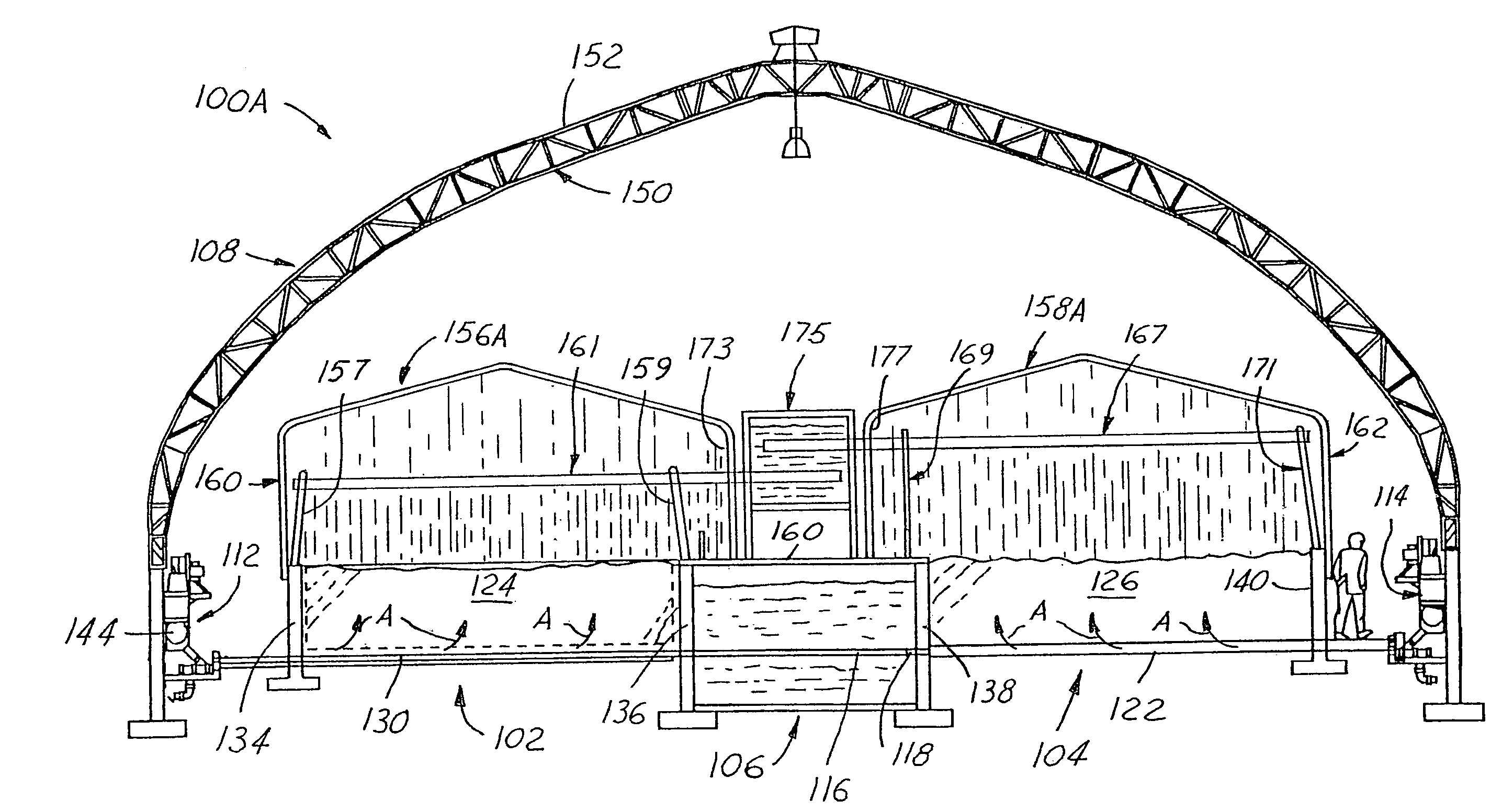
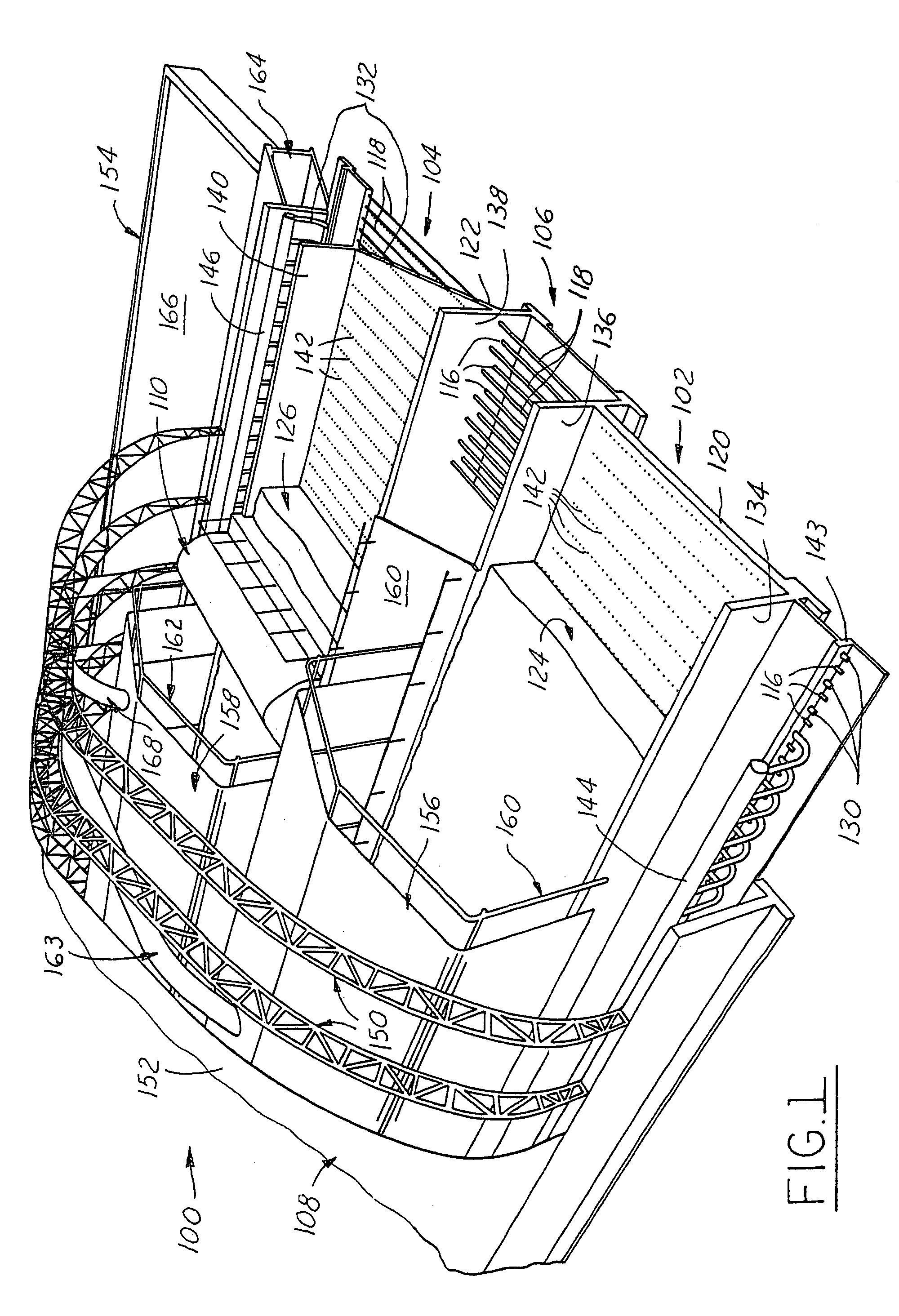
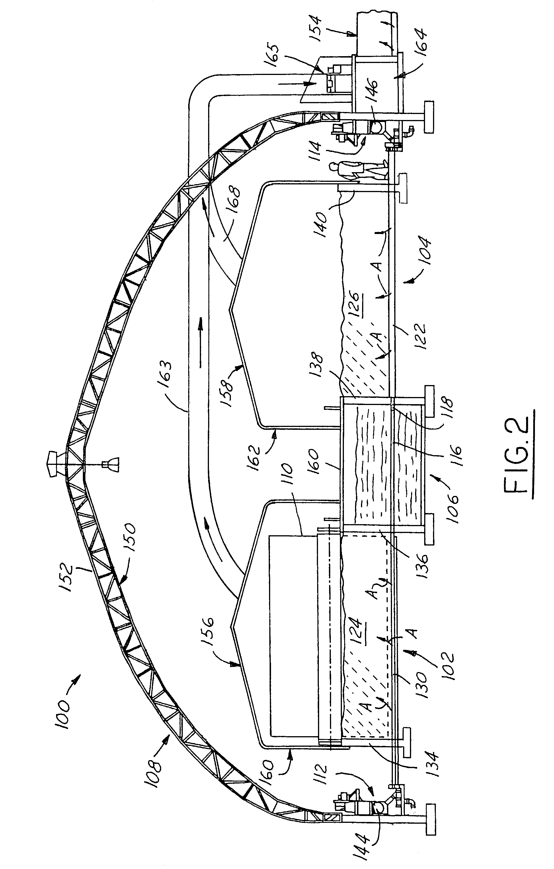
[0014]Accordingly, among the objects of the present invention are to provide an improved system, method and apparatus operable to economically produce heat energy in a controlled manner by decomposition of biomass material in an environmentally safe and sound manner and to automatically utilize such heat energy for hygienically heating a closed interior structure, such as a greenhouse, preferably without the requirement of any external power source or fuel other than the biomass material being decomposed.
[0015]In simplistic terms, one primary goal of the invention is to develop an economical, environmentally friendly heating system, which will promote and sustain plant growth within a greenhouse (or any other structure).
[0016]Another objective is to assist greenhouse and other agricultural, commercial and industrial operations in reducing dependency on natural gas as a primary energy source and to harvest the economic efficiencies of nature's own renewable biomass resources.
[0019]In this undertaking, and in developing the invention, a test apparatus was constructed as one of the foregoing embodiments of the invention to be used on a continuing basis as a container to promote, monitor, and regulate the decomposition of various selected biomass materials. Heat energy generation properties from the biological decomposition process were evaluated using a variety of organic matrixes while, at the same time, a heat transfer and distribution mechanism was customized to the application requirements of this batch-type process for complimenting the natural exertion of microbial activity. One important goal has been to ascertain a readily available biomass material that will slowly decompose while it generates a substantial quantity of usable heat energy to be consumed in the elevation of temperature in a separated confinement area. The operating environment for this decomposition process is monitored and sometimes regulated to successfully enhance heat generation performance and maximize biomass decomposition service lifetime.

Problems solved by technology

However, so far as is known, such systems have not been designed, utilized and controlled to primarily develop heat energy for hygienically heating an air space of an enclosed structure, such as a greenhouse, in a passive manner through a self-powered heat transfer mechanism from a biomass material heat generating source.
However, environmental and economical restrictions have impeded these developments within the commercial industry.
Burning biomass, in itself, can be viewed as an inefficient use of energy; the fuel is consumed quickly, causing a rapid energy release, much of which can be lost up the exhaust stacks.
However, harvesting this heat energy source for a commercial use such as greenhouse heating, presents new challenges.
However, this particular method of composting may not be practical for the purpose pursued in the system of the invention because of the constant need to, in mushroom operations, mechanically aerate by turning and fluffing the piles or windrows.
This form of composting is very rapid, causing the components to be “consumed” very quickly.
The underlying challenge in each case is to establish composting systems that will function within the designed confinement criteria.

Method used


Image

  • Biomass heating system
  • Biomass heating system
  • Biomass heating system

Examples


second embodiment

Thermal Engine Plant Second Embodiment

[0104]FIGS. 3, 4 and 5 illustrate a second embodiment thermal engine plant 200 similar in construction to plant 100 of FIGS. 1 and 2, and those components that are identical to components of the first embodiment are given identical reference numerals and their description not repeated. Thermal engine plant 200 employs a “negative” air flow system, the negative air flow being indicated by the arrows “B” shown in FIG. 4. With a negative air flow system in plant 200, it will seen that there are no internal tent coverings, membranes or tarpaulin structures over the two compost troughs or channels 102 and 104. Instead, the air or atmosphere drawn off from the masses of composting materials 124 and 126 flows down through these masses and is drawn off at the bottom of these masses through the concrete-embedded air conduits 130 and 132 interposed between and paralleling the concrete-embedded heat pipes 116 and 118. Air conduits 130 communicate with a he...

third embodiment

[0108]FIGS. 6, 7 and 8 are semi-schematic layouts of a biofilter air heating system and water heating system third embodiment of the present invention, in which both heat energy and carbon dioxide, as well as warm moist air produced by the composting action, are utilized in a greenhouse. The thermal energy plant portion of this system is designated by the general reference numeral 300 and the associated adjacent greenhouse by the reference numeral 302.

[0109]It will be seen from FIG. 7 that air is taken from the floor area of greenhouse 302 and drawn from it through a blower or air compressor 304 and then exhausted from that blower and forced via outlet duct 306 through a series of manifold distributor ducts 308 buried under a large concrete pad 310 on which the biomass material 312 is placed. Concrete pad 310 is perforated so that outlets 315 of air ducts 314 penetrate pad 310 and are oriented to blow air upwardly into biomass 312, oxygenating it as the air passes therethrough. As t...

fourth embodiment

Biomass Heating System

[0118]FIGS. 9 and 10 are respectively a plan view and side view in simplified diagrammatic format of a fourth embodiment thermal engine plant 400 of a composting heat recovering process using biomass feedstock deployed in an “open-air” (i.e., uncovered) set-up, also in accordance with the invention. Plant system 400 features a compost turner 408 and a conveyor 414 used for dumping the thermally spent biomass and thus resembles thermal engine plant 300 except that it is open-air and simplified with a reduced number of components.

[0119]More particularly, thermal engine plant 400 again uses a concrete slab or pad 402 segmented into twelve troughs or “vessels”404 by means of six-foot high sidewalls 406. These walls 406 separate the vessels into the separate “compost bays”404 and act as tracks for an engine driven compost turner 408 which, by use of tines, fluffs the feedstock, allowing aeration so as to promote decomposition and therefore heat generation. Turner 40...


PUM

PropertyMeasurementUnit
temperaturesaaaaaaaaaa
temperatureaaaaaaaaaa
poweraaaaaaaaaa

Abstract

Improved systems, methods, apparatus and compositions for generating, extracting and distributing the renewable heat energy produced by microbial decomposition of organic biomass within a contained and controlled environment. This heat energy is preferably transferred and distributed, preferably by the use of heat pipes, to the interior of a greenhouse or other structure to be heated, either directly or via heat exchange apparatus such as hot water heating systems. In one embodiment heat transfer and distribution mechanism customized to the application requirements of a greenhouse heating batch-type process is disclosed, along with a recipe for a readily available biomass material composition that will slowly decompose while it generates a substantial quantity of usable heat energy to be consumed in the elevation of temperature in a separated greenhouse basement confinement area. Additional continuous and batch process embodiments of biomass heating systems are also disclosed that extract heat energy from decomposing biomass for heating uses. In some embodiments gaseous products generated in a biological decomposition process, primarily CO2, are utilized to enhance plant growth in the greenhouse environment.

Description

[0001]This is a United States regular utility patent application filed pursuant to 35 U.S.C. §111(a) and claiming the benefit under the provisions of 35 U.S.C. §119(e)(1) of now abandoned U.S. provisional utility patent applications Ser. No. 60 / 304,949 filed Jul. 12, 2001; Ser. No. 60 / 337,896 filed Nov. 5, 2001 and Ser. No. 60 / 379,915 filed May 13, 2002, all of the aforesaid U.S. provisional patent applications being incorporated by reference in toto herein.FIELD OF THE INVENTION[0002]This invention relates to methods and apparatus for aerobically decomposing organic materials, primarily agricultural and foodstuff waste products, for the production primarily of heat energy and secondarily fertilizer and other by-products.BACKGROUND OF THE INVENTION[0003]Many methods and apparatus are known in the art for the purpose of decomposing, in an economical and environmentally acceptable manner, waste products resulting from agricultural and forestry, vegetable production and horticulture, l...

Claims


Application Information

Patent Timeline
Patent Type & Authority Patents(United States)
IPC IPC(8): C05F17/02C05F17/00F24J3/00F24V30/00
CPCC05F17/0063C05F17/0235C05F17/0258F24J3/00F28D15/0275F24V99/00C05F17/939C05F17/964C05F17/60Y02P20/133Y02P20/145Y02W30/40
Inventor OUELLETTE, JOSEPH P.
Owner AGRILAB TECH INC
Why Eureka
Eureka Blog
Learn More