
Backheating method and backheating structure for heat pump air conditioner

A heat pump air conditioner and heat exchanger technology, applied in heating methods, air conditioning systems, heat recovery systems, etc., can solve problems such as increased friction between fluid and wall surface, increased irreversible loss, complex heat recovery structure, etc., to achieve stable refrigerant flow state, Effect of reducing irreversible loss and improving cooling or heating performance

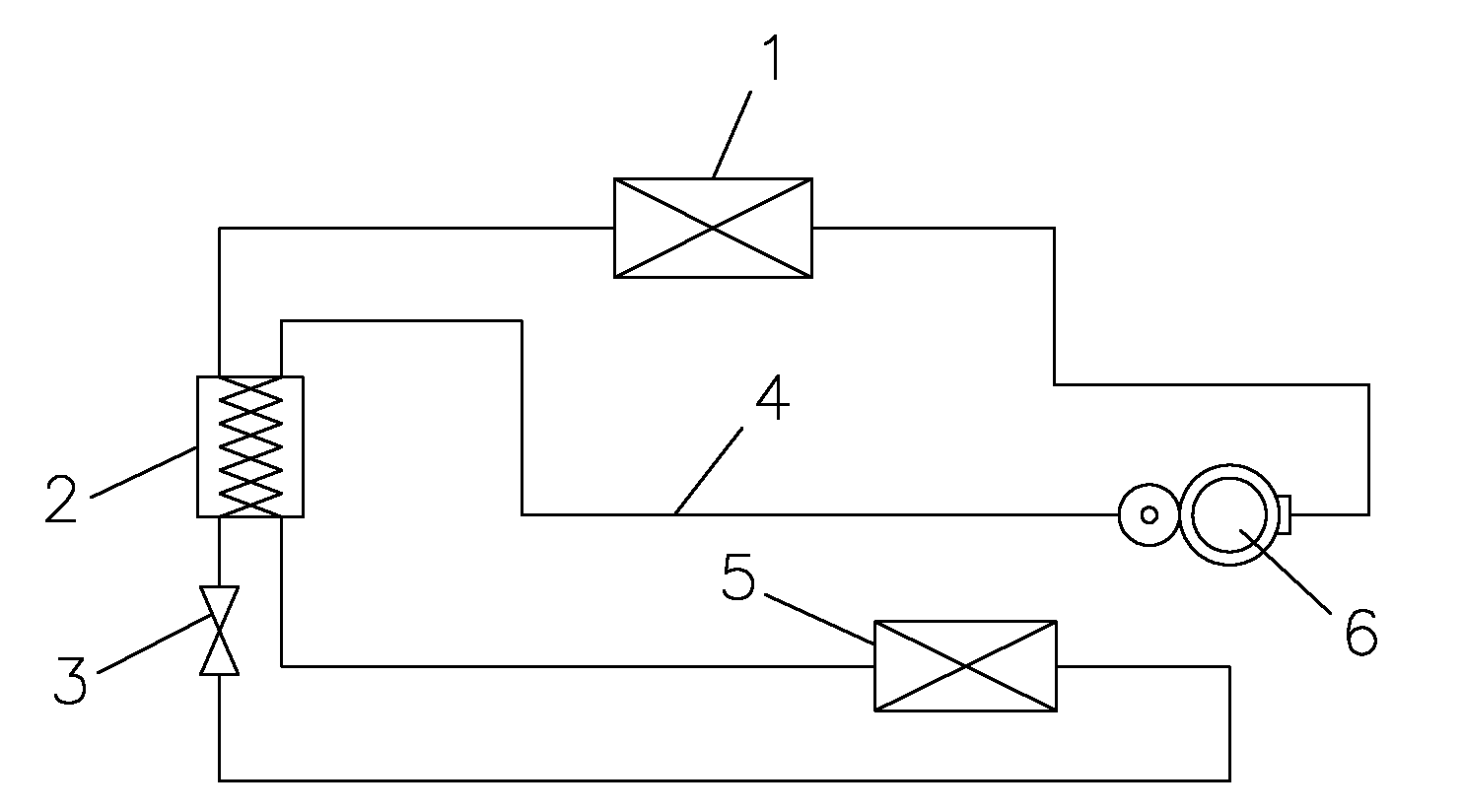
Inactive Publication Date: 2011-02-23
四川长虹空调有限公司
View PDF3 Cites 30 Cited by
  • Summary
  • Abstract
  • Description
  • Claims
  • Application Information

AI Technical Summary

Problems solved by technology

[0004] Although the above heat recovery method can increase the subcooling degree of the refrigerant before throttling to a certain extent, reduce the superheat degree of the evaporator outlet, minimize the temperature difference of the refrigerant before and after throttling, reduce the throttling loss, and improve the performance of the air conditioner. However, there are still problems of relatively complex heat recovery structure and high manufacturing cost
[0005] In addition, during the throttling process, after the single-phase refrigerant enters the throttling element from the condenser, due to the severe friction between the high-speed fluid and the inner surface of the throttling element, the pressure and temperature of the refrigerant continue to drop. When the pressure drops below the saturation pressure corresponding to the temperature When the refrigerant becomes two phases, the dryness increases continuously, and its density decreases continuously. However, since the mass and flow rate remain unchanged, the flow rate of the refrigerant will also increase continuously, and may reach a critical flow state, which makes the fluid and the wall The friction increases and the irreversible loss increases
This question has not been asked yet

Method used


Image

  • Backheating method and backheating structure for heat pump air conditioner
  • Backheating method and backheating structure for heat pump air conditioner
  • Backheating method and backheating structure for heat pump air conditioner

Examples


Embodiment 1

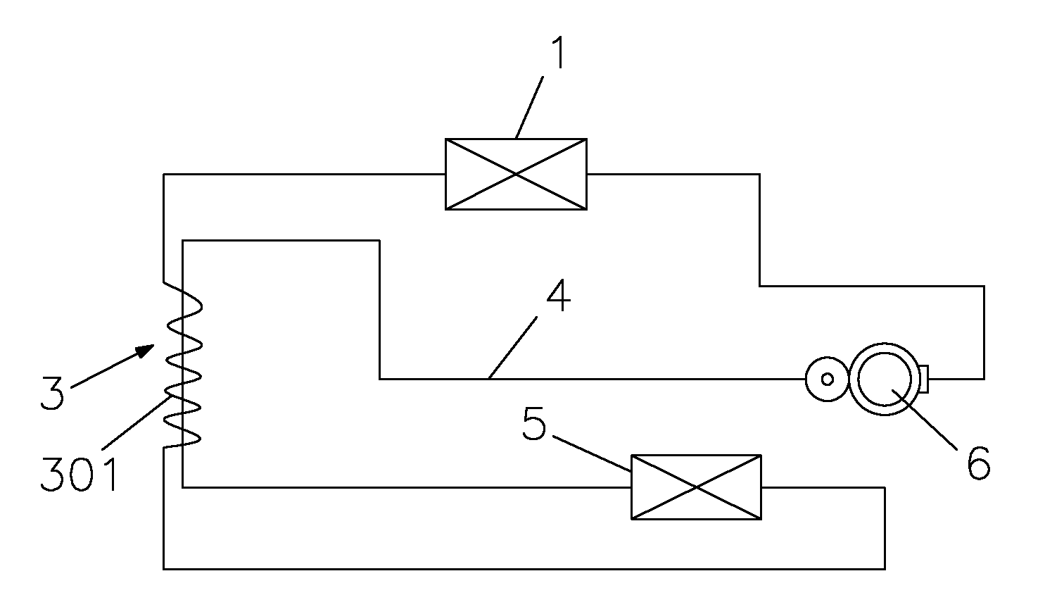
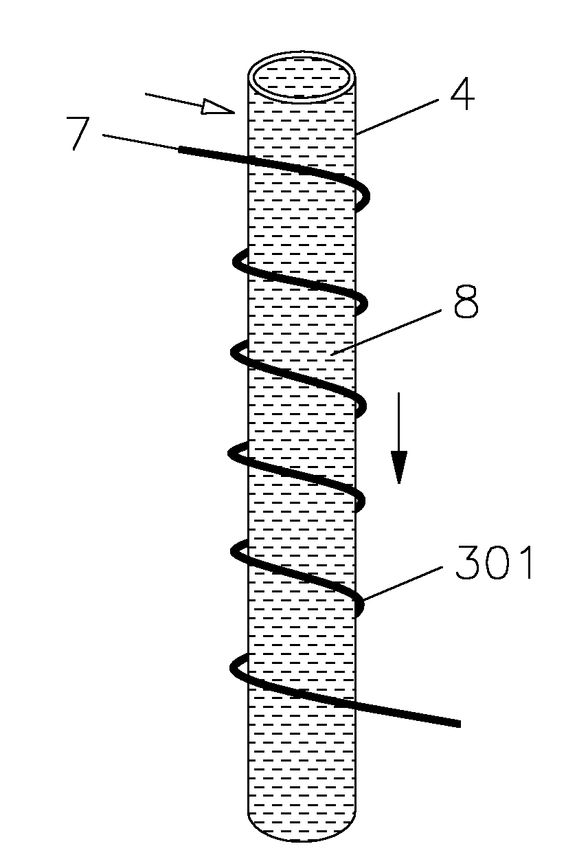
[0023] Such as image 3 As shown, the throttle capillary 301 is wound on the outer wall of the compressor suction pipe 4 . combine figure 2 and image 3 As shown, when the heat pump air conditioner is in the cooling mode or the heating mode, the relatively high-temperature refrigerant 7 enters the throttling capillary 301 from the heat exchanger A1 (acting as a condenser at this time), thereby being sucked together with the compressor while throttling. The relatively low-temperature refrigerant 8 in the gas pipe 4 performs heat exchange, and the throttled refrigerant enters the heat exchanger B5 (at this time as an evaporator) for evaporation and heat exchange. After the heat exchange, the relatively low-temperature refrigerant 8 enters the suction pipe of the compressor 4. It also exchanges heat with the relatively high-temperature refrigerant 7 that is throttling from the heat exchanger A1, and finally returns to the compressor 6 for recompression, thereby completing the ...

Embodiment 2

[0026] Such as Figure 4 As shown, the throttling capillary 301 is placed in the lumen of the compressor suction pipe 4, and the two ends of the throttling capillary 301 protrude from the compressor suction pipe 4 to connect with the heat exchanger A1 and the heat exchanger B5 respectively. combine figure 2 and Figure 4 As shown, when the heat pump air conditioner is in the cooling mode or the heating mode, the relatively high-temperature refrigerant 7 enters the throttling capillary 301 from the heat exchanger A1 (acting as a condenser at this time), thereby being sucked together with the compressor while throttling. The relatively low-temperature refrigerant 8 in the gas pipe 4 performs heat exchange, and the throttled refrigerant enters the heat exchanger B5 (at this time as an evaporator) for evaporation and heat exchange. After the heat exchange, the relatively low-temperature refrigerant 8 enters the suction pipe of the compressor 4. It also exchanges heat with the r...


PUM


Abstract

The invention discloses a backheating method and a backheating structure for a heat pump air conditioner, which can improve the performance of the air conditioner. The backheating structure comprises heat exchangers A and B, a compressor, and a throttling element connected between the heat exchangers A and B, wherein the heat exchanger B is connected with the compressor by an air suction pipe of the compressor; and a higher-temperature coolant in the throttling element performs heat exchange with a lower-temperature coolant in the air suction pipe of the compressor. In the backheating method and the backheating structure, the temperature of the coolant in the throttling element can be reduced by performing backheating in a throttling process, thereby retarding the evaporation of the coolant and the change of the dryness of the coolant, making more stable the flow regime of the coolant and reducing inevitable loss; and the dryness of the coolant at an outlet of the throttling element is reduced, namely, the degree of subcooling of the air conditioner is increased, so the cooling capacity of the air conditioner can be improved. The backheating method and the backheating structure for the heat pump air conditioner can improve the cooling or heating performance of the heat pump air conditioner; and the backheating structure is simplified to a certain extent so as to be convenient to manufacture and save the cost.

Description

technical field [0001] The invention relates to a heat recovery method and a heat recovery structure of a heat pump air conditioner. Background technique [0002] The existing heat recovery method adopted in the air conditioning system is to exchange heat between the low-temperature gaseous refrigerant at the outlet of the evaporator and the high-temperature liquid refrigerant at the outlet of the condenser, so as to reduce the temperature of the high-temperature liquid refrigerant and increase the subcooling degree of the refrigerant. Therefore, this recuperation method must perform recuperation before throttling. [0003] The basic regenerative structure to implement the method, reflected in figure 1 Above, it consists of heat exchanger A (as a condenser at this time), heat exchanger B (as an evaporator at this time), a compressor, a throttling element connected between heat exchanger A and heat exchanger B, and a The regenerator between the throttling element and the he...

Claims


Application Information

Patent Timeline
Patent Type & Authority Applications(China)
IPC IPC(8): F25B41/04F24F5/00F25B41/06F25B40/06
CPCY02B30/52Y02B30/123
Inventor 李峰杨涛徐博李冬
Owner 四川长虹空调有限公司
Learn More