
NF3 production reactor

a production reactor and nitrogen trifluoride technology, applied in the direction of machines/engines, lighting and heating apparatus, separation processes, etc., can solve the problems of accelerated corrosion at the impeller tip, significant problems remain, and localized overheating, so as to reduce corrosion

Inactive Publication Date: 2006-10-31
BOC GRP INC
View PDF11 Cites 6 Cited by
  • Summary
  • Abstract
  • Description
  • Claims
  • Application Information

AI Technical Summary

Benefits of technology

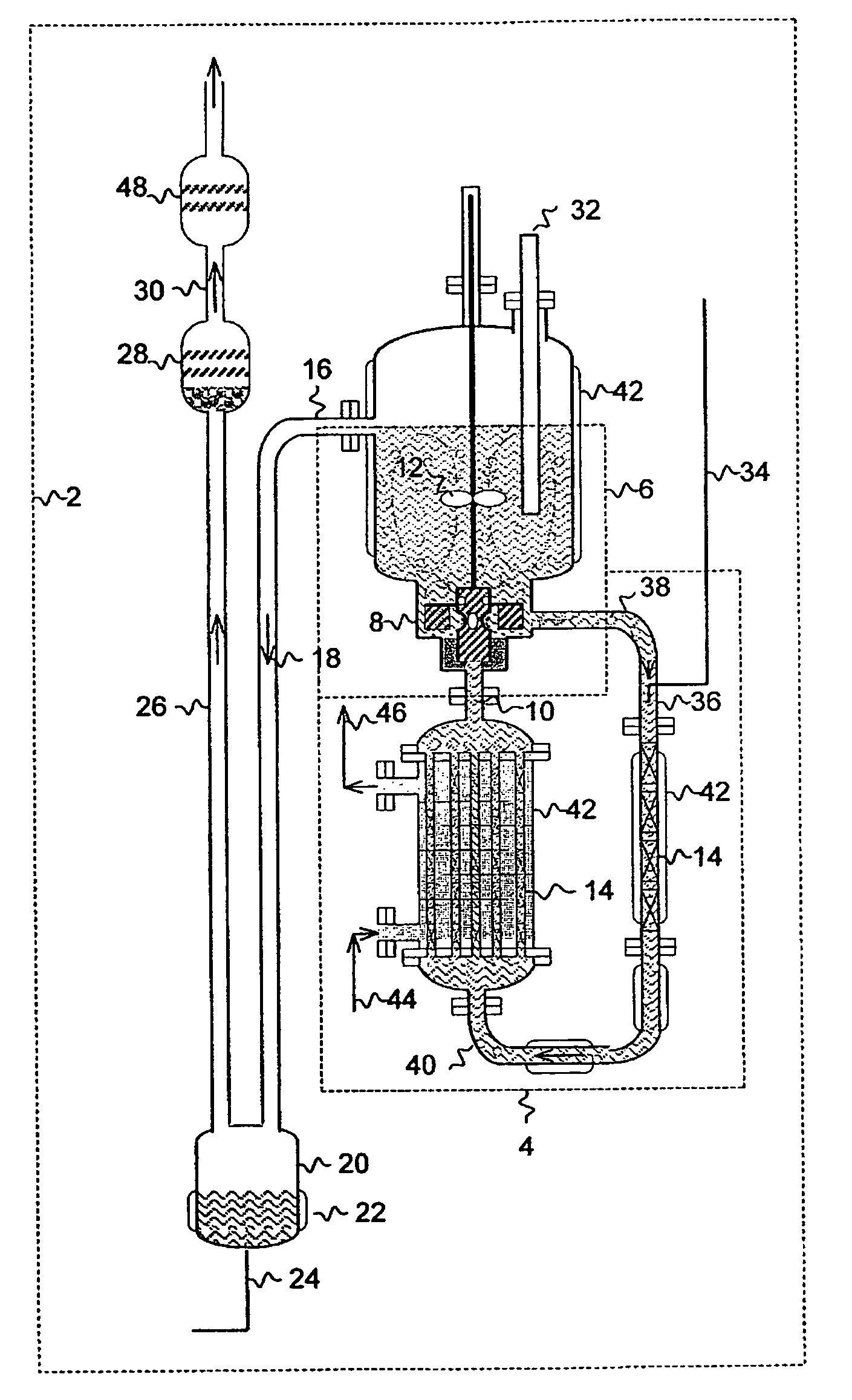
[0010]The present invention is generally directed to the production of NF3 by reacting fluorine gas, ammonia gas and liquid ammonium acid fluoride. The present invention provides a process in which low energy input is provided in vicinity of relatively high concentration of the corrosive reactant fluorine gas and higher energy input is provided in vicinity of relatively low concentrations of fluorine. As a consequence of the present invention, a NF3 producing system is provided with improved yields of NF3 without excessive corrosion of the mixing assembly. The balancing of energy input and fluorine concentration creates a reaction environment that is less conducive to corrosion. In particular, the aspect ratio of the reaction zones and the power input supplied to the reaction zones are selected to construct reaction zones in which conditions which tend to cause corrosion (e.g. high shear rates, high energy input, and high concentration of fluorine gas) are balanced with conditions that tend to favor low corrosion (low shear rates, low energy input, and low concentrations of fluorine gas).
[0015]b) reacting the first reaction product including the unreacted fluorine gas in a second reaction zone in a relatively high energy environment to produce a second reaction product, wherein the low energy environment in the first reaction zone and the high energy environment in the second reaction zone substantially convert the fluorine gas to NF3 in a manner which at least substantially decreases corrosion in the first and second reaction zones due to the corrosive properties of the fluorine gas.

Problems solved by technology

Although U.S. Pat. No. 5,637,285 achieves improvements in NF3 yield, some significant problems remain.
First, the highly exothermic NF3 reaction is most rapid at the impeller tip, which causes localized overheating, accelerated corrosion at the impeller tip, and mechanical reliability problems.
Second, one can not increase the solution depth, to increase the gas residence time, without increasing the mixing shaft length, which also increases mechanical reliability problems.
However, this approach does not address the issue concerning the impeller shaft length or the combination of high mixing rates and high fluorine concentration.
In addition, the NH4F(HF)x melt recirculation rate is limited by gaseous product flow rate and gas-liquid separation.

Method used


Image

  • NF3 production reactor
  • NF3 production reactor
  • NF3 production reactor

Examples


Embodiment Construction

[0019]The present invention is directed to a process for producing NF3 from a reaction mixture containing fluorine gas and liquid ammonium acid fluoride. As will be described below, the reaction is conducted in two reaction zones characterized as having different energy environments. The energy environment in the first reaction zone where the concentration of fluorine gas is relatively high is characterized as being a relatively low energy environment. The energy environment in the second reaction zone where the concentration of fluorine gas is less than the first reaction zone (i.e. because at least in part some of the fluorine gas has reacted in the first reaction zone) is characterized as being a relatively high energy environment.

[0020]The term “relatively high energy environment” shall mean a reaction zone in which reaction conditions and / or features of the reaction zone are selected to provide more energy at the location of the fluorine gas reactant than would appear in a rela...


PUM

PropertyMeasurementUnit
Temperatureaaaaaaaaaa

Abstract

A process for the production of nitrogen trifluoride by reacting fluorine gas and liquid ammonia acid fluoride in a first reaction zone having a relatively low energy input followed by treatment of the resulting reaction product in a second reaction zone having a relatively high energy input. The resulting crude nitrogen trifluoride product may be further treated with fluorine gas under elevated temperatures to improve yield of the desired product.

Description

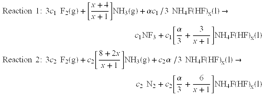
CROSS REFERENCE TO RELATED APPLICATION[0001]This application claims priority of U.S. Provisional Patent Application No. 60 / 436,070 filed on Dec. 23, 2002.FIELD OF THE INVENTION[0002]The present invention relates generally to nitrogen trifluoride and more particularly to a reactor system and a method for the production of nitrogen trifluoride from ammonia, elemental fluorine, and liquid ammonium acid fluoride.BACKGROUND OF THE INVENTION[0003]Nitrogen trifluoride (NF3) has been employed for such products as high energy liquid and solid propellants and as a fluorine source for the production of semiconductor devices. Nitrogen fluoride can be prepared by a variety of processes such as disclosed in U.S. Pat. Nos. 4,091,081 and 5,637,285 and U.S. Patent Publication No. 2002 / 0127167 each of which is incorporated herein by reference. The production of nitrogen trifluoride generally results from a series of reactions as described below in which ammonia and fluorine gas are combined with a li...

Claims


Application Information

Patent Timeline
IPC IPC(8): C01B21/06B01F5/06B01F5/10B01F7/00B01F7/16B01F13/10B01J8/06B01J19/00B01J19/18B01J19/24C01B21/083
CPCB01F5/106B01F13/103B01J8/06B01J19/006B01J19/0066B01J19/1881B01J19/2425C01B21/0835B01F5/0602C01P2006/80B01F7/16B01J2219/00006B01J2219/0004B01J2219/00085B01J2219/00247B01F25/42B01F25/53B01F27/80B01F33/8212C01B21/083
Inventor SATCHELL, JR., DONALD P.
Owner BOC GRP INC
Learn More