
Accessing and updating a configuration database from distributed physical locations within a process control system

a technology of process control and configuration database, which is applied in the field of process control system configuration database, can solve the problems of reducing the speed of accessing data, reducing the number of reads, and not being able to connect the different sites using a common dedicated bus

Inactive Publication Date: 2006-10-24
FISHER-ROSEMOUNT SYST INC
View PDF35 Cites 65 Cited by
  • Summary
  • Abstract
  • Description
  • Claims
  • Application Information

AI Technical Summary

Benefits of technology

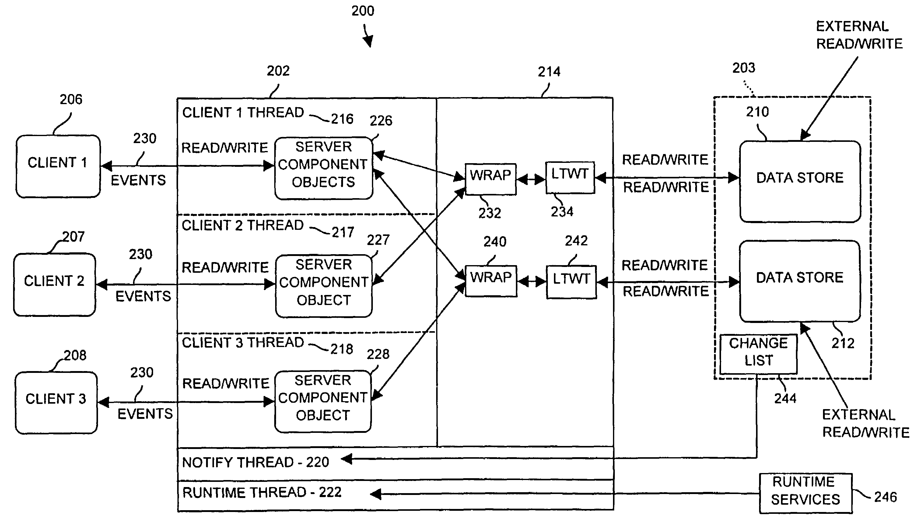
[0011]A configuration database distribution, access and alteration strategy is provided to enable numerous geographically separated locations of a process control system to be integrated together using a common configuration database in a manner that enables users at each of the different locations to view and change the configuration database in a timely, secure and non-conflicting manner, even when the different locations of the process control system are communicatively connected via a low bandwidth or slow (i.e., delayed) communication link or are only intermittently communicatively connected via, for example, a modem connection.
[0013]To prevent configuration data being viewed by users within the process control system from becoming stale, the configuration database access system at each location may automatically send changes made to the configuration database to each of the users currently viewing that data so that the user views the state of the configuration as it actually exists in the configuration database. In one embodiment, each portion of the configuration database includes a data access routine that uses a shared cache to coordinate the delivery of configuration components to each of the users or subscribers currently viewing that data in a way that reduces the number of reads to the configuration database, which increases the speed of accessing data from the configuration database. This shared cache may incorporate a locking mechanism to enable locking and reservation of components within the configuration database. If desired, the configuration information obtained by each user may be stored locally to enable the user to view the configuration information even if the communication link to the configuration database storing the master copy of that information goes down or otherwise becomes unavailable.

Problems solved by technology

When integrating multiple geographically separated sites, however, it is practically, if not actually, impossible to connect the different sites using a common dedicated bus, such as the Ethernet bus, due to the distances involved.
However, satellite, cellular and other wide area wireless communication links are typically very expensive to use and, if used, are generally shared so that they can only provide a limited amount of bandwidth when compared to a dedicated bus, such as an Ethernet bus.
Likewise, the Internet, T1 lines and other shared wide area networks provide only a limited amount of bandwidth or throughput and are, therefore, typically very slow for data transfer when compared to a dedicated Ethernet local area network bus.
Still further, the geographical distance between the different sites and the need to provide secure and assured communications between the sites using, for example, acknowledgments of data packets, as provided in the IP, TCP and UDP communication protocols, further add to the delay of communications between the sites.
As a result of the delay in communications between geographically diverse sites of a process control system and the increase in the number of user interfaces or other devices accessing a configuration database, it is difficult to provide a configuration database that stores the data for the entire process control system, including the devices in each of the geographically diverse sites in a manner that can be accessed in a fashion by users at all of the different sites and in a manner that can altered by users at the different sites using current configuration database accessing procedures.
Specifically, if the configuration database is located at a main site, users at a remote site will have to download all of the configuration data on a refresh basis over the slow or remote link, which may take an inordinate amount of time.
Still further, the sheer increase in the number of users accessing the configuration database may increase the access time to any piece of information within the configuration database to an unacceptable level.
Likewise, when reconfiguring the process control system, the delay in communications between a main site and a remote site may enable two different users to try to reconfigure the same component of the process control system leading to confusion and error.
In the meantime, however, a user at the main site may reconfigure the same portion of the process control system and, because there is relatively no delay in communications at the main site, may store this new configuration in the configuration database before the user at the remote site attempts to send new configuration data generated at the remote site to the configuration database for storage, which leads to errors.
In some cases, it may not be possible or practical to even provide a slow or low bandwidth communication link between different sites, in which case configuration of a remote site has to occur at the remote site and then has to be uploaded to the configuration database at the main site.
However, this off-line configuration can cause problems if different users try to reconfigure the remote site at or near the same time, or if a user tries to reconfigure a remote site before another user who has already reconfigured the remote site updates the configuration database to reflect the changes already made to the remote site.

Method used


Image

  • Accessing and updating a configuration database from distributed physical locations within a process control system
  • Accessing and updating a configuration database from distributed physical locations within a process control system
  • Accessing and updating a configuration database from distributed physical locations within a process control system

Examples


Embodiment Construction

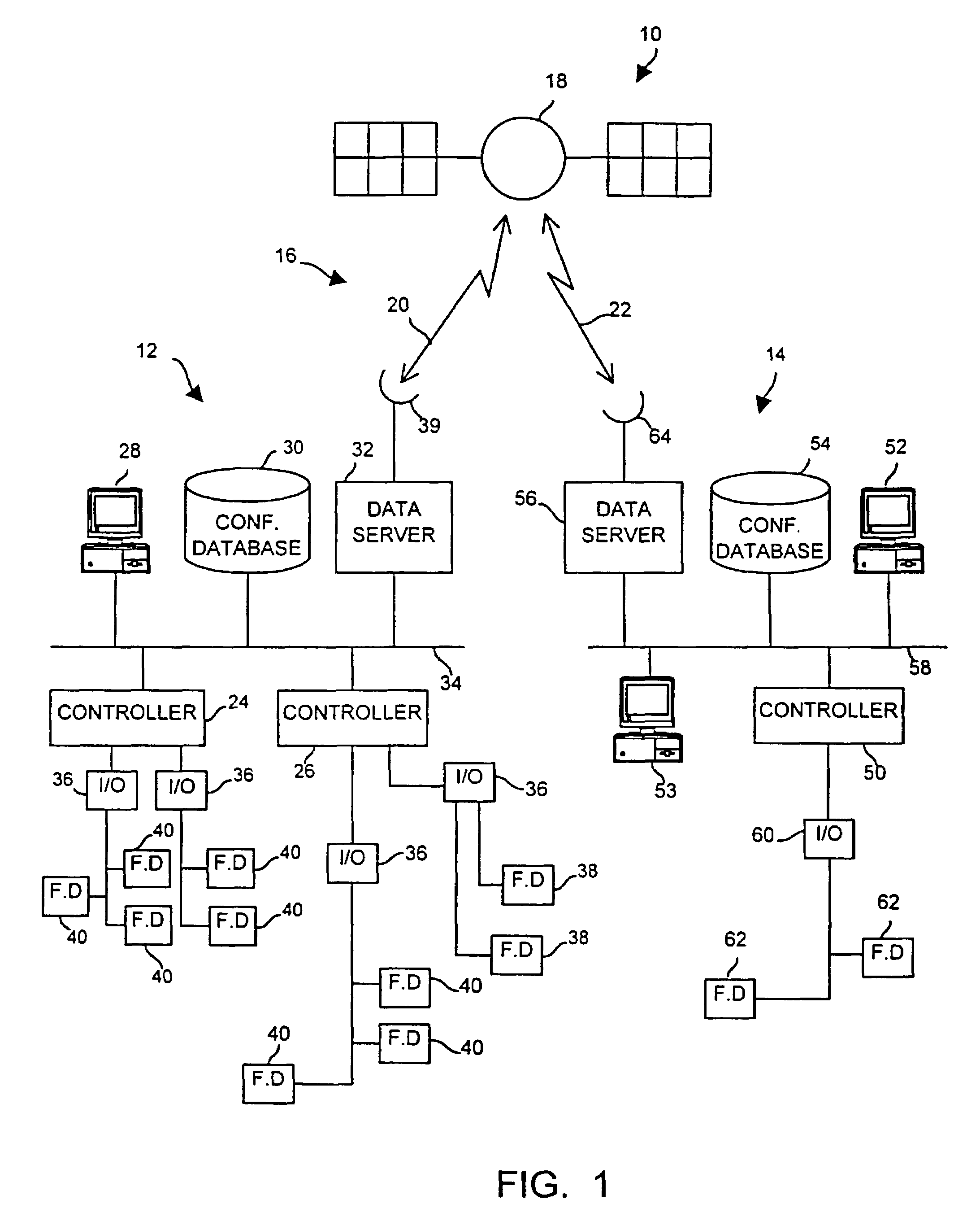
[0029]Referring now to FIG. 1, a process control system 10 includes geographically separated sites or locations 12 and 14 communicatively connected via a satellite communication link 16 formed by a satellite 18 having a first uplink / downlink channel 20 and a second uplink / downlink channel 22 which may be two way channels. The first site 12, which will be referred to herein as the local or main site 12, includes two process controllers 24 and 26 connected to a user interface 28, a configuration database 30 and a data server 32 via a dedicated local area network bus 34 which may be, for example an Ethernet or any other desired bus or communication line. The user interface 28 may be any desired type of host workstation or computer, such as any type of personal computer, laptop computer, etc. while the configuration database 30 may be a stand-alone database device or may be integrated into any other device, such as the user interface 28 or the data server 32. The data server 32 includes...


PUM


Abstract

A configuration database includes multiple databases distributed at a plurality of physical locations within a process control system. Each of the databases may store a subset of the configuration data and this subset of configuration data may be accessed by users at any of the sites within the process control system. A database server having a shared cache accesses a database in a manner that enables multiple subscribers to read configuration data from the database with only a minimal number of reads to the database. To prevent the configuration data being viewed by subscribers within the process control system from becoming stale, the database server automatically detects changes to an item within the configuration database and sends notifications of changes made to the item to each of the subscribers of that item so that a user always views the state of the configuration as it actually exists within the configuration database.

Description

RELATED APPLICATIONS[0001]This is a divisional application of U.S. patent application Ser. No. 09 / 560,199 entitled “Accessing and Updating a Configuration Database from Distributed Physical Locations within a Process Control System” which was filed on Apr. 28, 2000 now U.S. Pat. No. 6,687,698.[0002]This is a regular filed application based on Provisional Application Ser. No. 60 / 160,104 filed Oct. 18, 1999 entitled “Accessing and Updating a Configuration Database From Distributed Physical Locations Within a Process Control System.”FIELD OF THE INVENTION[0003]The present invention relates generally to process control systems and, more particularly, to a process control configuration system having a configuration database that can be accessed and updated from geographically distributed physical locations within a process control system.DESCRIPTION OF THE RELATED ART[0004]Process control systems, like those used in chemical, petroleum or other processes, typically include at least one p...

Claims


Application Information

Patent Timeline
Patent Type & Authority Patents(United States)
IPC IPC(8): G06F17/30G06F9/445G05B19/414G06F12/00G06F13/00
CPCG05B19/4145G05B2219/31324G05B2219/31418G05B2219/31422G05B2219/33125G05B2219/36103Y10S707/99932Y10S707/99953Y10S707/99938Y02P90/02G05B19/0426
Inventor NIXON, MARKCHATKOFF, TERESAGILBERT, STEPHEN
Owner FISHER-ROSEMOUNT SYST INC
Learn More