
Carbon monoxide selective oxidizing catalyst and manufacturing method for the same

a technology of carbon monoxide and catalyst, which is applied in the direction of physical/chemical process catalyst, sustainable manufacturing/processing, and separation processes, etc., can solve the problems of reducing the efficiency of reducing the concentration of carbon monoxide in the fuel gas supplied to the fuel cell, affecting the performance of the cell, and affecting the efficiency of reducing the concentration of carbon monoxid

Inactive Publication Date: 2006-08-22
TOYOTA JIDOSHA KK
View PDF32 Cites 4 Cited by
  • Summary
  • Abstract
  • Description
  • Claims
  • Application Information

AI Technical Summary

Benefits of technology

[0010]One object of the invention is to provide a superior technology for reducing the concentration of carbon monoxide contained in a hydrogen-rich gas that contains carbon monoxide, like a reformed gas.
[0024]According to the carbon monoxide selective oxidizing catalysts in the above-mentioned aspects of the invention, and the carbon monoxide selective oxidizing catalysts manufactured in the above-mentioned aspects of the invention, it is possible to achieve a higher carbon monoxide reduction rate when the carbon monoxide concentration in the hydrogen-rich gas is reduced.
[0027]According to the carbon monoxide selective oxidizing catalysts in the above-mentioned aspects of the invention, and the carbon monoxide selective oxidizing catalysts manufactured in the above-mentioned aspects of the invention, it is possible to achieve a higher carbon monoxide reduction rate when the carbon monoxide concentration in the hydrogen-rich gas is reduced. In addition, a carbon monoxide selective oxidizing catalyst may be manufactured by supporting a transition element on the carrier in addition to platinum (Pt). Such a carbon monoxide selective oxidizing catalyst can achieve a sufficiently high carbon monoxide reduction rate even when the reaction temperature of the carbon monoxide selective oxidizing reaction is set at a lower value. Since a high carbon monoxide reduction rate can be achieved even when the reaction temperature is set at a lower value, it is possible to perform the carbon monoxide selective oxidizing reaction at a temperature that can sufficiently suppress activity of undesirable reactions. This improves the efficiency of reducing the carbon monoxide concentration in the hydrogen-rich gas. Since the efficiency of reducing the carbon monoxide concentration is improved, it becomes possible to build a more compact apparatus provided with the carbon monoxide selective oxidizing catalyst.
[0028]According to the above-mentioned aspects of the invention, it is possible to improve the selectivity in selectively oxidizing only the carbon monoxide when the carbon monoxide concentration in the hydrogen-rich gas is reduced, which improves the efficiency of reducing the carbon monoxide concentration in the hydrogen-rich gas. If the hydrogen-rich gas in which the carbon monoxide concentration is reduced using the carbon monoxide selective oxidizing catalyst is supplied to the fuel cell, the fuel cell catalyst can be prevented from being poisoned by carbon monoxide, and thus the cell performance can be maintained at a high level.

Problems solved by technology

However, in a fuel cell provided with a platinum-based catalyst such as a proton-exchange membrane fuel cell, if the supplied gas contains carbon monoxide, the catalyst may be poisoned by carbon monoxide and the cell performance may deteriorate.
However, even in a case where the above-mentioned carbon monoxide selective oxidizing catalyst is used, the performance of reducing the concentration of the carbon monoxide contained in the fuel gas supplied to the fuel cell may be insufficient.
Therefore, in general, as the reaction temperature becomes higher, the oxidizing reaction of hydrogen becomes more active, thereby decreasing the efficiency of reducing the carbon monoxide concentration.
This results in a problem that the fuel utilization efficiency decreases.
In addition, as the reaction temperature becomes higher, undesirable reactions (for example, a methanation reaction that methanates hydrogen) become more active to consume more hydrogen, in addition to the carbon monoxide selective oxidizing reaction.
This causes a problem that the fuel utilization efficiency decreases.

Method used


Image

  • Carbon monoxide selective oxidizing catalyst and manufacturing method for the same
  • Carbon monoxide selective oxidizing catalyst and manufacturing method for the same
  • Carbon monoxide selective oxidizing catalyst and manufacturing method for the same

Examples


examples 1 , 2

(A) EXAMPLES 1, 2

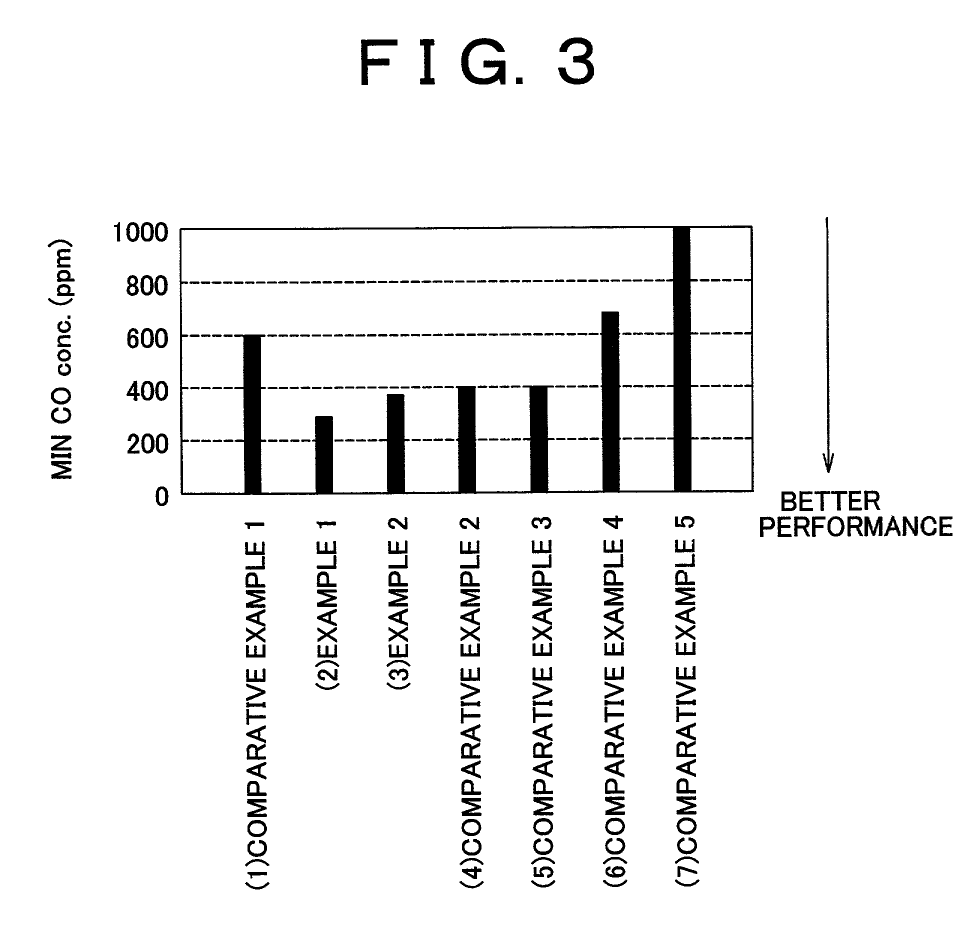
[0072]In Examples 1 and 2, a carrier including ferrierite or ZSM-5 was used in a carbon monoxide selective oxidizing catalyst provided with Pt. The carbon monoxide selective oxidizing catalysts (1) to (7) described below were compared in terms of catalytic performance. The catalysts (1) to (7) are listed in ascending order in terms of the pore diameter in the carrier.

[0073](1) Comparative Example 1: A catalyst in which Pt was supported on an A-type zeolite carrier [Pt (3 wt %) / A];[0074](2) Example 1: A catalyst in which Pt was supported on a ferrierite carrier [Pt (3 wt %) / Fer];[0075](3) Example 2: A catalyst in which Pt was supported on a ZSM-5 carrier [Pt (3 wt %) / ZSM-5];[0076](4) Comparative Example 2: A catalyst in which Pt was supported on a mordenite carrier [Pt (3 wt %) / Mor];[0077](5) Comparative Example 3: A catalyst in which Pt was supported on a zeolite β carrier [Pt (3 wt %) / β];[0078](6) Comparative Example 4: A catalyst in which Pt was supported on a USY...

examples 3 to 7

(B) EXAMPLES 3 to 7

[0092]In Examples 3 through 7, in carbon monoxide selective oxidizing catalysts using ferrierite as carriers thereof, various types of transition metals were supported on the carriers in addition to Pt. In a catalyst in Example 3, iron (Fe) was supported on a ferrierite carrier together with Pt. In a catalyst in Example 4, nickel (Ni) was supported on a ferrierite carrier together with Pt. In a catalyst in Example 5, cobalt (Co) was supported on a ferrierite carrier together with Pt. In a catalyst in Example 6, manganese (Mn) was supported on a ferrierite carrier together with Pt. In a catalyst in Example 7, copper (Cu) was supported on a ferrierite carrier together with Pt.

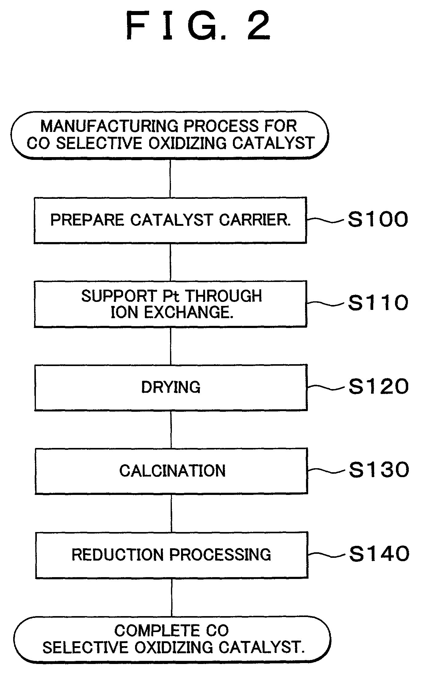
[0093]In the cases of the catalysts in Examples 3 through 7, steps S100 and S110 in the manufacturing process shown in FIG. 2 were performed to support Pt on the ferrierite carriers. Then, drying and calcination were performed on the carriers on which Pt was supported in steps S120 and S130. Fu...

examples 8 to 11

(C) EXAMPLES 8 to 11

[0098]In Examples 8 through 11, the content of Fe supported on the carrier together with Pt was changed. FIG. 7A shows the results in the case where the above-mentioned catalyst in Example 1 (FIG. 6B) was used and the molar ratio of Pt to Fe in Example 1 was 3:0 (no Fe). FIG. 7B shows the results in the case where the catalyst in Example 8 was used, and the molar ratio of Pt to Fe was 3:0.2 (the molar ratio value between Pt and Fe is 15). FIG. 7C shows the results in the case where the catalyst in Example 9 was used, and the molar ratio of Pt to Fe was 3:0.5 (the molar ratio value between Pt and Fe is 6). FIG. 8A shows the results in the case where the catalyst in Example 10 was used, and the molar ratio of Pt to Fe was 3:1.0 (the molar ratio value between Pt and Fe is 3). FIG. 8B shows the results in the case where the catalyst in Example 11 was used, and the molar ratio of Pt to Fe was 3:2.0 (the molar ratio value between Pt and Fe is 1.5). The catalyst in Exam...


PUM

PropertyMeasurementUnit
pore diameteraaaaaaaaaa
temperatureaaaaaaaaaa

Abstract

A carbon monoxide selective oxidizing catalyst includes a carrier of ferrierite or ZSM-5 that supports a metal component of platinum (Pt) alone or platinum and at least one type of transition metal. Alternatively, a carbon monoxide selective oxidizing catalyst includes a carrier whose maximum pore diameter ranges from 0.55 to 0.65 nanometers (nm) that supports a metal component of platinum (Pt) alone or platinum and at least one type of transition metal.

Description

INCORPORATION BY REFERENCE[0001]The disclosure of Japanese Patent Application No. 2001-060060 filed on Mar. 5, 2001, including the specification, drawings and abstract is incorporated herein by reference in its entirety.BACKGROUND OF THE INVENTION[0002]1. Field of Invention[0003]The invention relates to carbon monoxide selective oxidizing catalysts that promote a reaction of oxidizing carbon monoxide by giving carbon monoxide priority over hydrogen and manufacturing methods for the same.[0004]2. Description of Related Art[0005]A reformed gas obtained by reforming gasoline or a hydrocarbon-based fuel such as natural gas or alcohol is employed as a hydrogen-rich fuel gas used in an electrochemical reaction in a fuel cell. Such a reformed gas generally contains a certain amount of carbon monoxide. However, in a fuel cell provided with a platinum-based catalyst such as a proton-exchange membrane fuel cell, if the supplied gas contains carbon monoxide, the catalyst may be poisoned by car...

Claims


Application Information

Patent Timeline
Patent Type & Authority Patents(United States)
IPC IPC(8): H01M8/22C01B3/32B01D53/02B01J29/064B01J29/068B01J29/076B01J29/40B01J29/44B01J29/46B01J29/67B01J29/68B01J29/69B01J37/18C01B3/40C01B3/58C10K3/04H01M8/06
CPCB01J29/068B01J29/44B01J29/46B01J29/67C01B3/583H01M8/0662H01M8/0668B01J29/68B01J29/064B01J29/076Y02E60/50C01B2203/044C01B2203/047Y02P70/50
Inventor KURACHI, SAEKO
Owner TOYOTA JIDOSHA KK
Learn More