Method for producing nitrogen trifluoride using jet-loop reactors

a technology of nitrogen trifluoride and reactor, which is applied in the direction of nitrogen and non-metal compounds, chemistry apparatus and processes, and ammonium fluoride, etc., can solve the problems of increasing the cost of gas, reducing the yield gradually with the passage of time, and not satisfying the nfsub>3 /sub>yield, etc., and achieves the effect of increasing the nf3 yield

Inactive Publication Date: 2006-08-01
KOREA INST OF SCI & TECH
View PDF12 Cites 7 Cited by
  • Summary
  • Abstract
  • Description
  • Claims
  • Application Information

AI Technical Summary

Benefits of technology

[0024]Accordingly, the present invention has been made to solve the above-mentioned problems occurring in the prior art, and an object of the present invention is to provide a method for producing NF3 by directly contacting gaseous fluorine with a fused ammonium fluoride salt, in which the fused...

Problems solved by technology

It is an expensive gas, which has been gradually and widespreadingly used in etching of silicon or silicon oxide layers and in dry cleaning of chemical vapor deposition (CVD) chambers in the manufacturing processes of the semiconductor or the liquid crystal display (LCD).
Though the document discloses that the yield of NF3 reaches 63% which is larger than 30˜50% that the former conventional documents have announced, it has a drawback in that the yield is gradually reduced with the passage of time.
However, this method requires a strong stirring force per unit volume of at least 4.5 kW/m3 for converting F2 up to 63%, so that the NF3 yield is not satisfied even while introducing an intense stirring force many times larger than that used in ordinary chemical reactors.
However, the solid reactants should be periodically replaced with new ones because they are difficult to be regenerated.
In addition, there is no proper method for safely discarding the solid waste matters.
Therefore, this method is not yet adopted industrially.
This method, however, has a drawback that since an explosion occurs if NF3 generated from an anode is mi...

Method used


Image

  • Method for producing nitrogen trifluoride using jet-loop reactors
  • Method for producing nitrogen trifluoride using jet-loop reactors
  • Method for producing nitrogen trifluoride using jet-loop reactors

Examples


embodiment 1

[0060]A. Apparatus

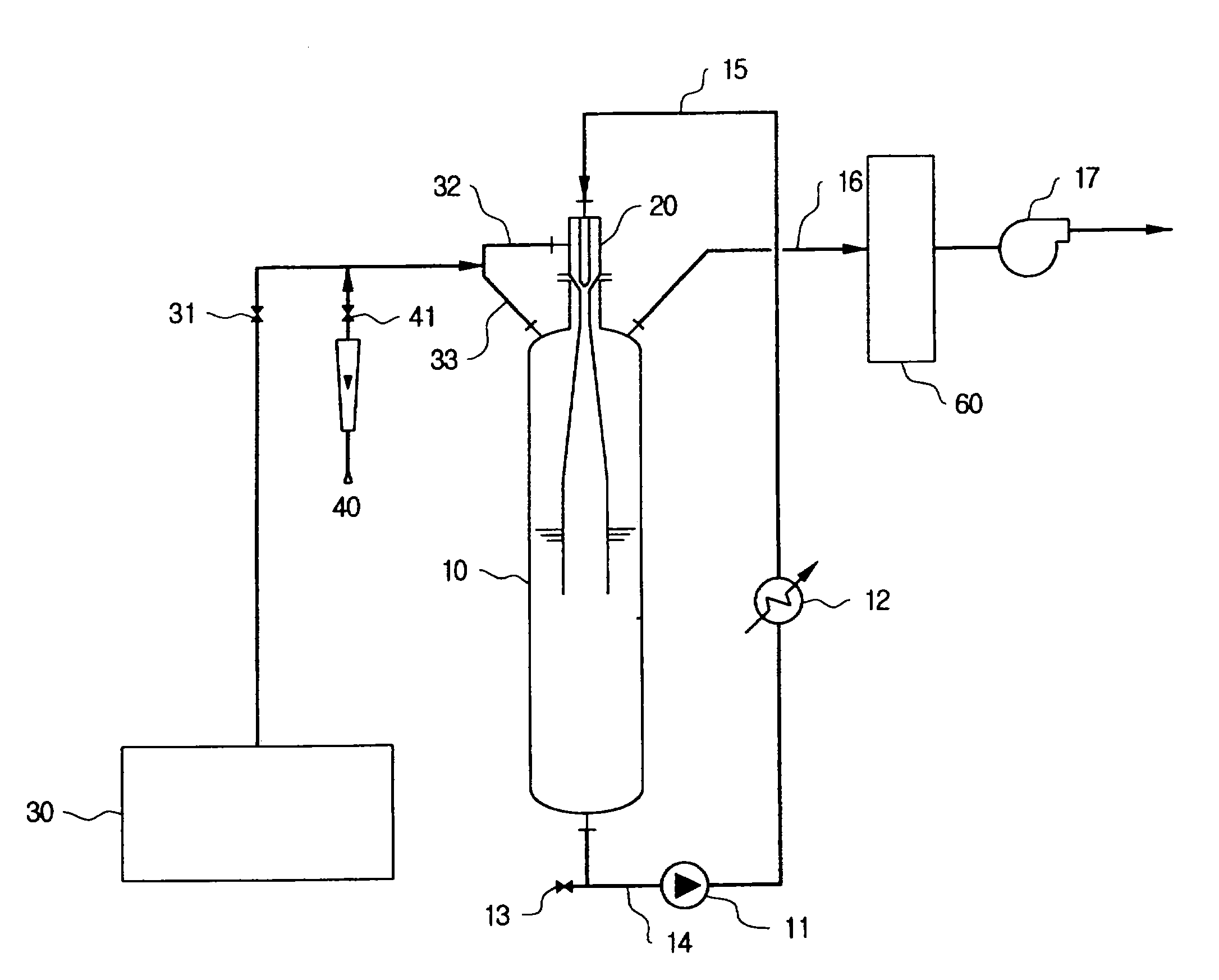
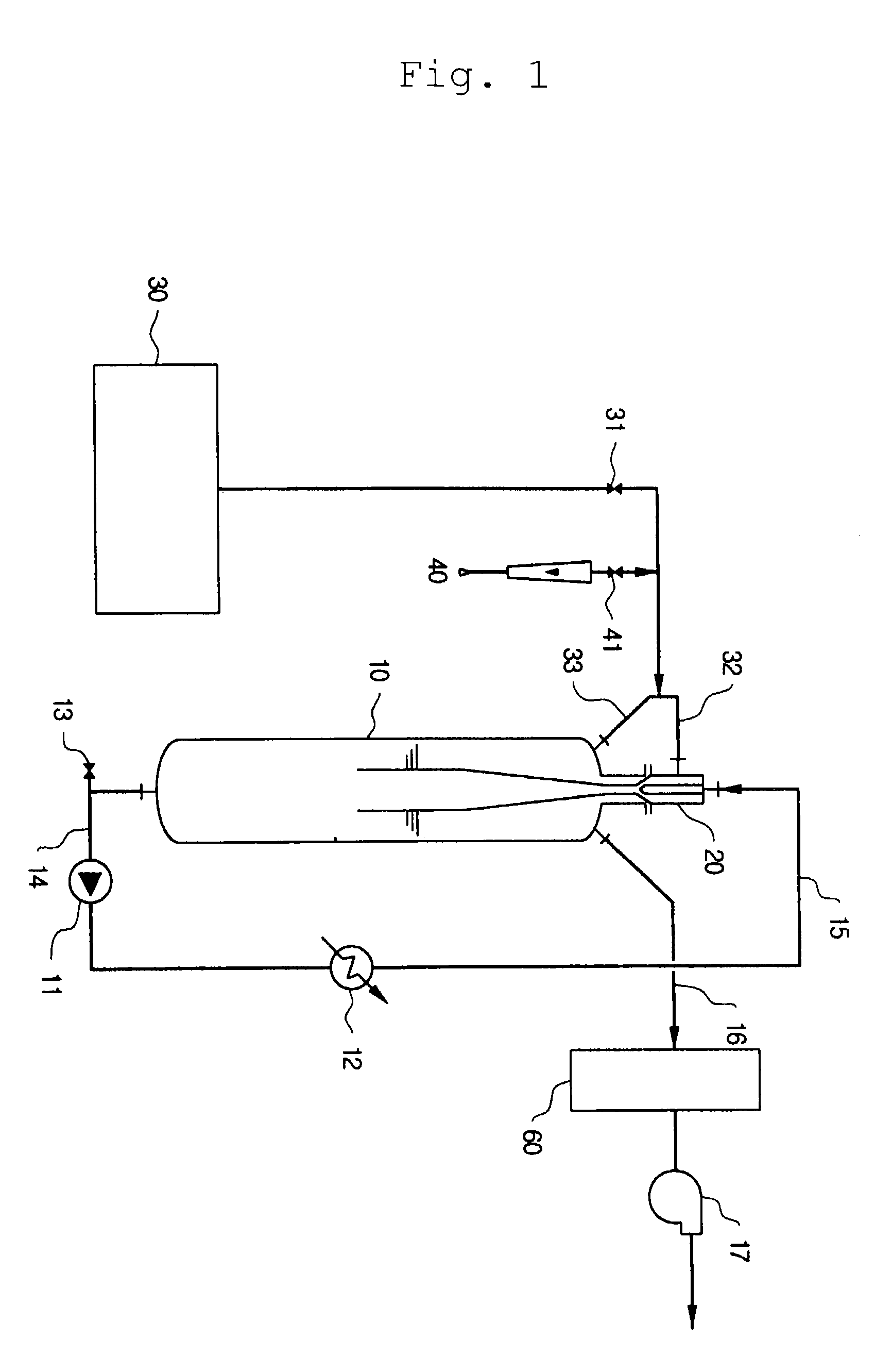
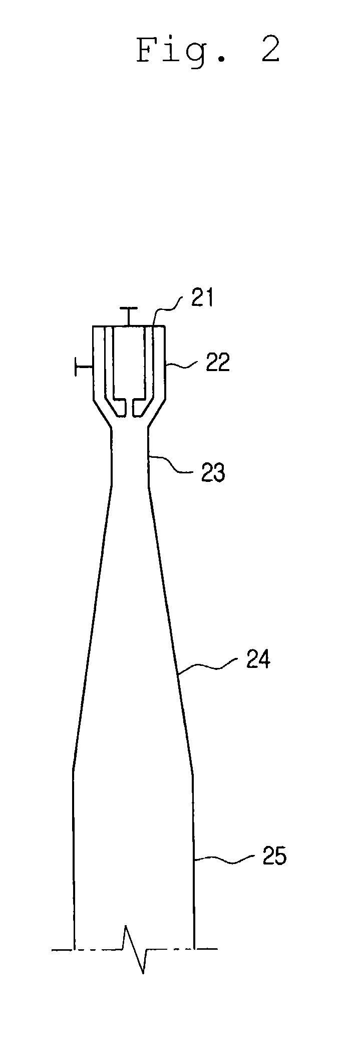
[0061]An experiment was conducted using an apparatus shown in FIG. 1. A reactor is a vertical tube type reactor having a diameter of 8 inch and a volume of 36 l, which has a jet ejector pipe installed thereon, in which a throat having seven nozzles are provided. Inner diameters of the throat and the nozzle are 15 mm and 1.8 mm, respectively, so that the ratio of the cross sectional area of the throat to the total cross sectional area of the nozzles in the jet enjector pipe is about 10.

[0062]B. Experiment

[0063](1) Production of a Fused Ammonium Fluoride Salt

[0064]25 Kg acidic ammonium fluoride salt (NH4F.HF) was introduced into the reactor and gases in the reactor were drawn out. 8 Kg HF was slowly supplied and temperature was raised to 120° C., thus producing a fused ammonium fluoride salt. Then, Ar gas was introduced into the reactor up to ambient pressure and the fused ammonium fluoride salt was circulated through the jet ejector pipe so as to provide an even con...

embodiments 2 to 6

[0076]The embodiments were conducted by the same apparatus and method as in the embodiment 1, except that a temperature range of the fused ammonium fluoride salt was changed to a range of 100˜150° C. The yield of NF3 and the conversion of F2 for a respective temperature were shown in the following Table 1.

[0077]

TABLE 1ReactionEmbodimentTemp. (° C.)Conversion of F2 (%)Yield of NF3 (%)210076.2 ± 1.374.7 ± 1.7311096.5 ± 0.593.6 ± 0.3112097.9 ± 0.393.0 ± 0.2413098.6 ± 0.289.7 ± 0.2514099.1 ± 0.284.2 ± 0.2615099.4 ± 0.180.5 ± 0.3

[0078]The conversion of F2 became higher along with the increase of temperature while the yield of NF3 had a maximum value at 110˜120° C. but was likely to be gradually reduced in the rest of the range. The production rate of NF3 per hour also had a maximum value at 110˜120° C., and the higher the reaction temperature was, the more amount of by-products, N2F2 and N2, was produced.

[0079]At a reaction temperature of 110˜120° C., the temperature of an acid-washing c...

embodiments 7 to 12

[0080]The embodiments were conducted by the same apparatus and method as in the embodiments 1 to 6, except that a molar ratio of HF / NH3 of the fused ammonium fluoride salt was set to 3.50˜3.56. Yield of NF3 and conversion of F2 for a respective temperature at the given molar ratio of HF / NH3 were shown in the following Table 2.

[0081]

TABLE 2ReactionEmbodimentTemp.(° C.)Conversion of F2 (%)Yield of NF3 (%)710060.3 ± 2.658.5 ± 3.7811078.9 ± 0.976.6 ± 0.8912083.2 ± 1.179.9 ± 0.71013085.4 ± 0.679.0 ± 0.51114088.9 ± 0.578.2 ± 0.41215090.4 ± 0.775.9 ± 0.5

[0082]Generally, if a concentration of HF of the fused ammonium fluoride salt was excessively high, both the yield of NF3 and the conversion of F2 were low as compared with the results of the embodiments 1 to 6. As for the conversion of F2, the higher was the reaction temperature, the more was it likely to increase as in the embodiments 1 to 6, and as for the yield of NF3, it had a maximum value at 120˜130° C. but was likely to gradually re...


PUM


Abstract

Nitrogen trifluoride is produced with a high yield by the method comprising forming a fast stream of micro droplets of a fused ammonium fluoride salt by rapidly ejecting the fused ammonium fluoride salt into a reactor through a nozzle while circulating the fused ammonium fluoride salt in the reactor from a lower portion to an upper portion; and contacting micro droplets of the fused ammonium fluoride salt with fluorine gas sucked in the reactor through a suction pipe for fluorine by a negative pressure formed around the nozzle due to an ejection of the fused ammonium fluoride salt, whereby excessive generation and regional accumulation of the heat of reaction are prevented, reducing the reaction temperature by 10˜30° C. compared with those of the existing methods, and a side reaction occurs only to a slight extent according to the lowered reaction temperature.

Description

CROSS REFERENCE TO RELATED APPLICATIONS[0001]The present application is claiming priority of Korean Patent Application No. 10-2002-0042542 filed on Jul. 19, 2002.BACKGROUND OF THE INVENTION[0002]1. Field of the Invention[0003]The present invention relates to a method for producing nitrogen trifluoride, and more particularly to a method for producing nitrogen trifluoride using jet-loop reactors, wherein fused ammonium fluoride salt is rapidly ejected through a nozzle so that the fluorine gas is sucked and well mixed in the fused ammonium fluoride salt ejected as a fast stream, thus producing nitrogen trifluoride in a high yield.[0004]2. Description of the Prior Art[0005]Nitrogen trifluoride (hereinafter called NF3) is a stable gas, that has little reactivity at room temperature. It is an expensive gas, which has been gradually and widespreadingly used in etching of silicon or silicon oxide layers and in dry cleaning of chemical vapor deposition (CVD) chambers in the manufacturing pro...

Claims


Application Information

Patent Timeline
IPC IPC(8): C01B21/06C01B21/083C01C1/16
CPCC01C1/162C01B21/0835C01B21/083
Inventor KWON, YOUNG-SOOKIM, HONG-GONLEE, SANG-DEUKLEE, JAE-WOOHONG, JONG-YEVLIM, HYUNG-SIKAHN, BYOUNG-SUNG
Owner KOREA INST OF SCI & TECH
Why Eureka
Try Eureka