Eureka AIR delivers breakthrough ideas for toughest innovation challenges, trusted by R&D personnel around the world.

Photo-fabrication apparatus

a technology of photo-fabrication and apparatus, which is applied in the direction of printing, manufacturing tools, instruments, etc., can solve the problems of deterioration of the shape accuracy of the physical model, increase in time and increase in the cost of physical model fabrication, etc., and achieves short time and high shape accuracy

Active Publication Date: 2006-08-01
DAINIPPON SCREEN MTG CO LTD
View PDF11 Cites 19 Cited by
  • Summary
  • Abstract
  • Description
  • Claims
  • Application Information

AI Technical Summary

Benefits of technology

[0007]The present invention is intended for a photo-fabrication apparatus which performs three-dimensional fabrication by irradiating a photosensitive material with light, and it is an object of the present invention to perform three-dimensional fabrication for a short time or with high accuracy of shape.
[0009]The above photo-fabrication apparatus can efficiently perform an exposure of the photosensitive material for three-dimensional fabrication for a short time with a plurality of micromirrors and improve the accuracy of shape of a physical model obtained after development by controlling the quantity of irradiation light for each exposure region among more than two levels.
[0011]The above photo-fabrication apparatus can improve the accuracy of shape of a physical model obtained after development by controlling the quantity of irradiation light for each exposure region among more than two levels and further allow a wide-range exposure for three-dimensional fabrication on the photosensitive material with the moving mechanism.
[0012]Preferably, the group of irradiation regions are arranged at regular intervals in two directions which are orthogonal to each other and a distance in a direction orthogonal to the relative movement direction between irradiation regions on both ends in a row along the one array direction is smaller than a pitch of the group of irradiation regions in the other array direction. This allows easy control of the spatial light modulator and an exposure with high accuracy.
[0014]The above photo-fabrication apparatus can improve the accuracy of shape of a physical model obtained after development by controlling the quantity of irradiation light for each exposure region among more than two levels and further allow a wide-range exposure for three-dimensional fabrication on the photosensitive material with the moving mechanism.
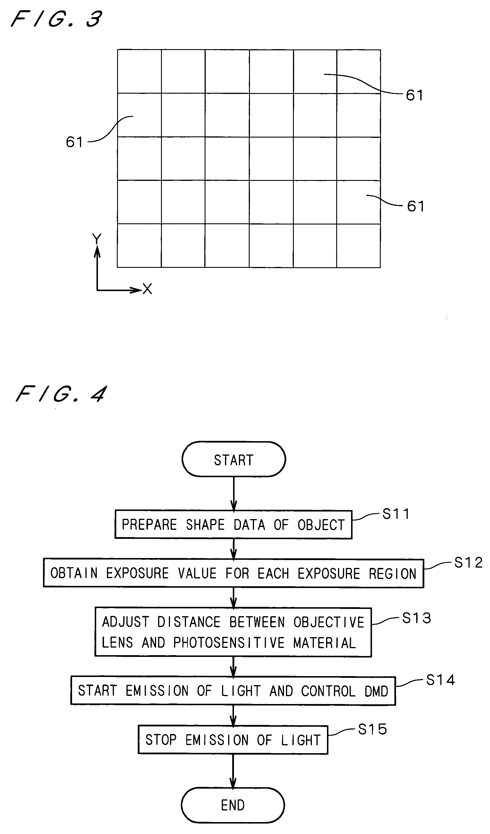
[0016]Further preferably, the photo-fabrication apparatus further comprises a measuring device, and in the photo-fabrication apparatus, a plurality of exposure regions are irradiated with light of different exposure values and the measuring device measures heights of a photosensitive material which is developed after irradiation, at the plurality of exposure regions, and the controller makes the table on the basis of the exposure values and the heights of photosensitive material at the plurality of exposure regions. This makes it possible to make a table with high accuracy.

Problems solved by technology

Since the conventional photofabrication, however, needs repeating lamination of the photocurable liquid resins and light irradiation, both time and cost for fabrication of physical models increase.
The technique disclosed in Japanese Patent Application Laid Open Gazette No. 2001-252986 disadvantageously deteriorates the accuracy in shape of physical model due to ill effect of lines between pixels of the liquid crystal mask and even in a case of fabrication of relatively large physical models, as the number of pixels is limited, the accuracy in shape of physical model is deteriorated.
This technique further has a problem of deterioration in efficiency of light irradiation due to liquid crystal.

Method used


Image

  • Photo-fabrication apparatus
  • Photo-fabrication apparatus
  • Photo-fabrication apparatus

Examples


Embodiment Construction

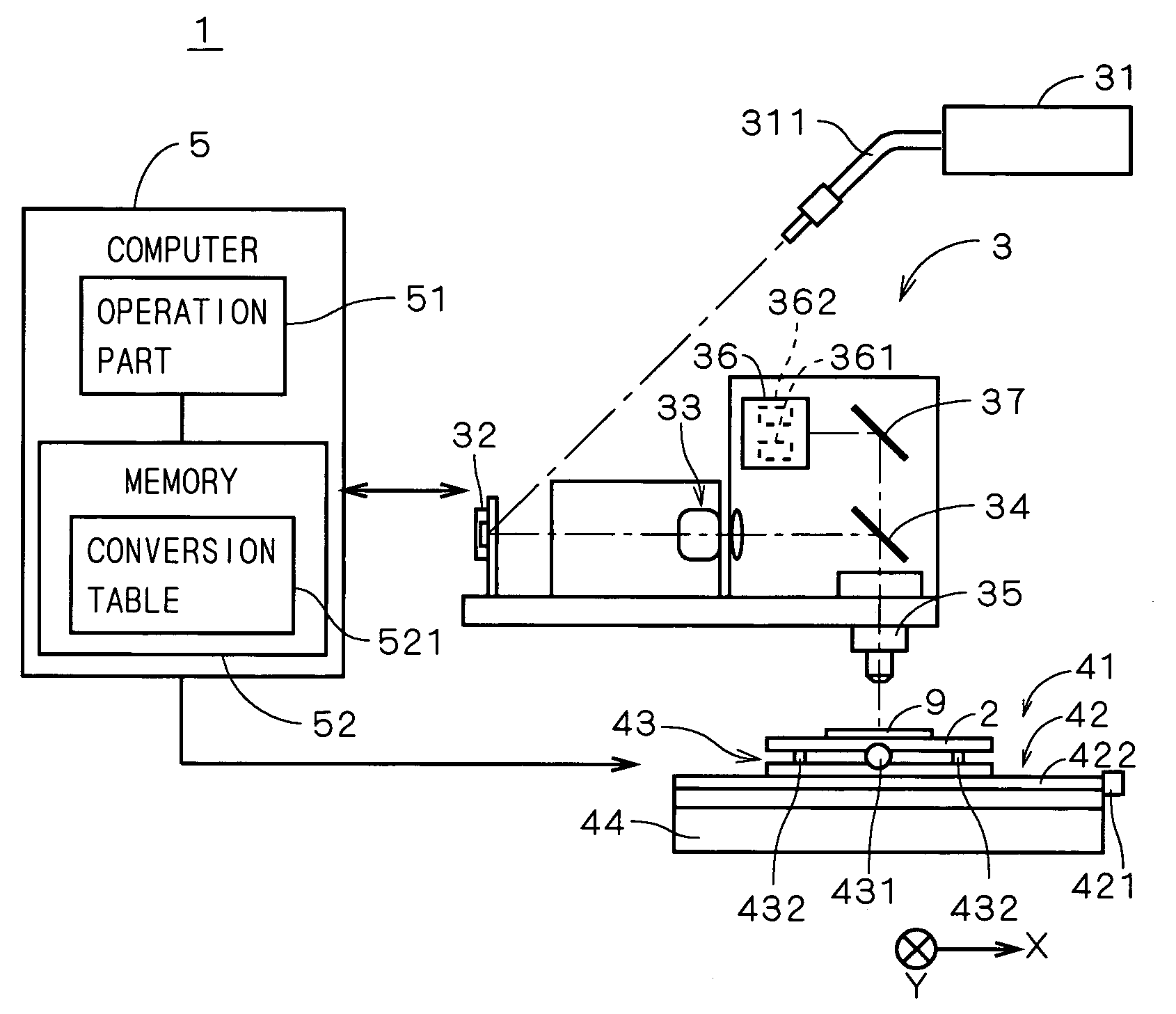
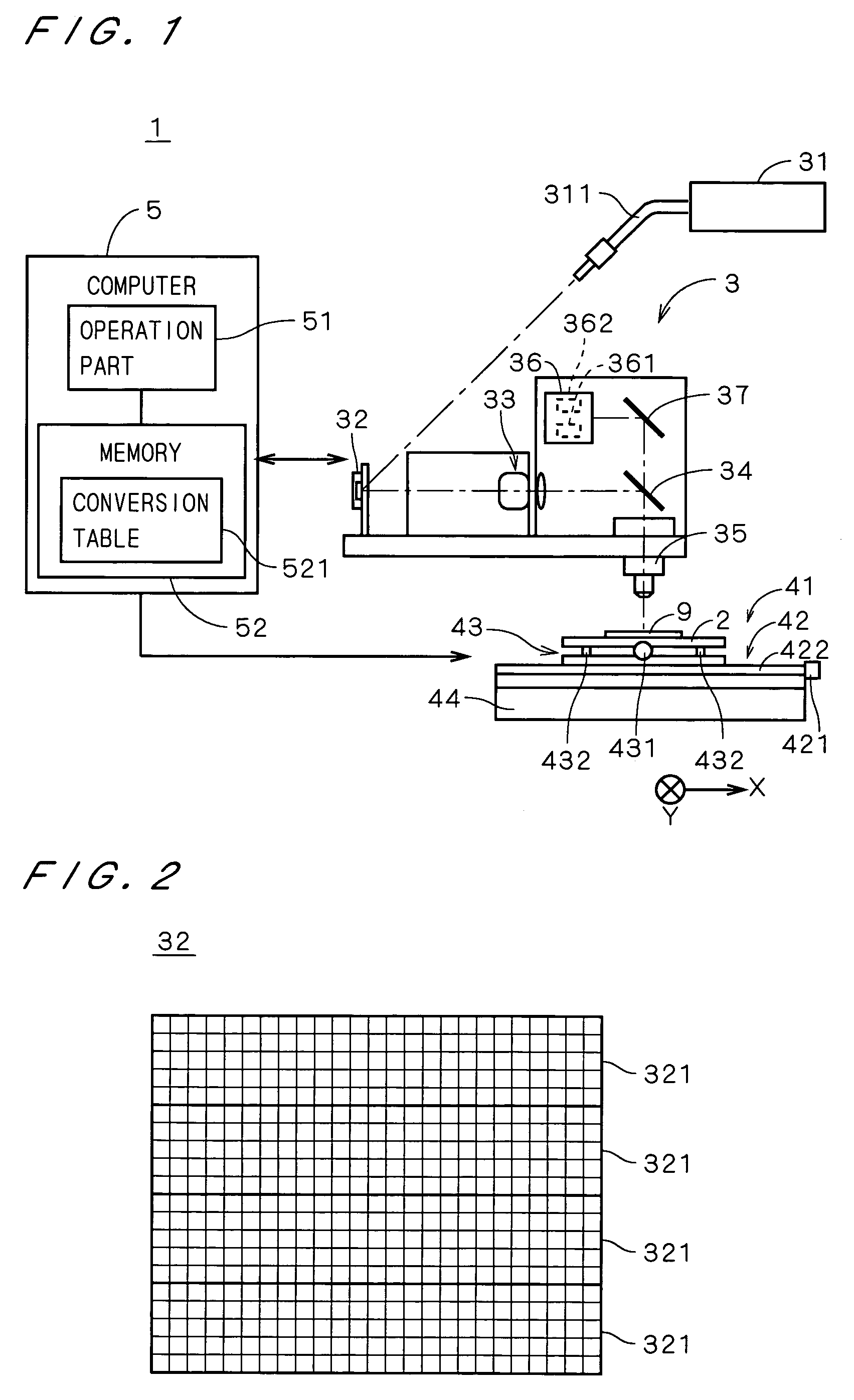
[0034]FIG. 1 is a view showing a construction of a photo-fabrication apparatus 1 in accordance with the first preferred embodiment of the present invention. The photo-fabrication apparatus 1 is an apparatus for irradiating a member with light in accordance with a 3D (three-dimensional) shape of a designed object (designed surface). The member is prepared in advance by coating a predetermined substrate with photosensitive resist which is a positive-type photosensitive material to have a predetermined film thickness and drying the coated substrate (hereinafter, the member is referred to simply as a “photosensitive member”). The exposed photosensitive member is developed in a later process to become a 3D physical model (3D physical surface).

[0035]The photo-fabrication apparatus 1 has a stage 2 for holding a photosensitive member 9, a head part 3 which is a unit for emitting a spatially-modulated light beam toward the photosensitive member 9, a stage moving mechanism 41 for moving the s...


PUM

PropertyMeasurementUnit
wavelengthaaaaaaaaaa
photosensitiveaaaaaaaaaa
tilt anglesaaaaaaaaaa

Abstract

A photo-fabrication apparatus comprises a stage for holding a photosensitive member which is a substrate coated with a photosensitive material, a head part for emitting a spatially-modulated light beam to said photosensitive member and a computer. The head part has a DMD having a plurality of micromirrors arranged in a two-dimensional array, and a light beam from a light source is reflected on only some of the group of micromirrors in the DMD which have a predetermined tilt angle and led onto the photosensitive member. In the photo-fabrication apparatus, the tilt angle of each micromirror in the DMD is controlled by the computer. This can control the quantity of irradiation light for an irradiation region on the photosensitive member corresponding to each micromirror, to perform an exposure in accordance with a three-dimensional shape of a desired object for a short time. The exposed photosensitive member is developed by another apparatus.

Description

BACKGROUND OF THE INVENTION[0001]1. Field of the Invention[0002]The present invention relates to a photo-fabrication apparatus for performing three-dimensional fabrication by irradiating a photosensitive material with light.[0003]2. Description of the Background Art[0004]Photofabrication has been conventionally performed, where 3D (three-dimensional) shape data of an object is sliced to obtain a plurality of cross-sectional data (i.e., 2D (two-dimensional) shape data) and while photocurable liquid resins are laminated, each of laminated layers is irradiated (exposed) with light on the basis of the corresponding cross-sectional data to fabricate a desired 3D model.[0005]Japanese Patent Application Laid Open Gazette No. 2001-252986 discloses a technique to fabricate a 3D model by irradiating a photocurable liquid resin with light which is spatially modulated by a liquid crystal mask without laminating the photocurable liquid resin.[0006]Since the conventional photofabrication, however...

Claims


Application Information

Patent Timeline
Patent Type & Authority Patents(United States)
IPC IPC(8): B28B17/00B29C67/00
CPCB29C67/0066B29C64/135
Inventor KOYAGI, YASUYUKISHIMOZUMA, HIROKO
Owner DAINIPPON SCREEN MTG CO LTD
Why Eureka
Eureka Blog
Learn More