
Thermoacoustic piezoelectric generator

a piezoelectric generator and piezoelectric technology, applied in the direction of generator/motor, machine/engine, lighting and heating apparatus, etc., can solve the problems of limiting the operating frequency of the engine, the penetration of the pressure vessel, and the sliding seal of the pressure vessel necessary for connecting rods and moving pistons,

Active Publication Date: 2006-07-25
PENN STATE RES FOUND
View PDF30 Cites 69 Cited by
  • Summary
  • Abstract
  • Description
  • Claims
  • Application Information

AI Technical Summary

Benefits of technology

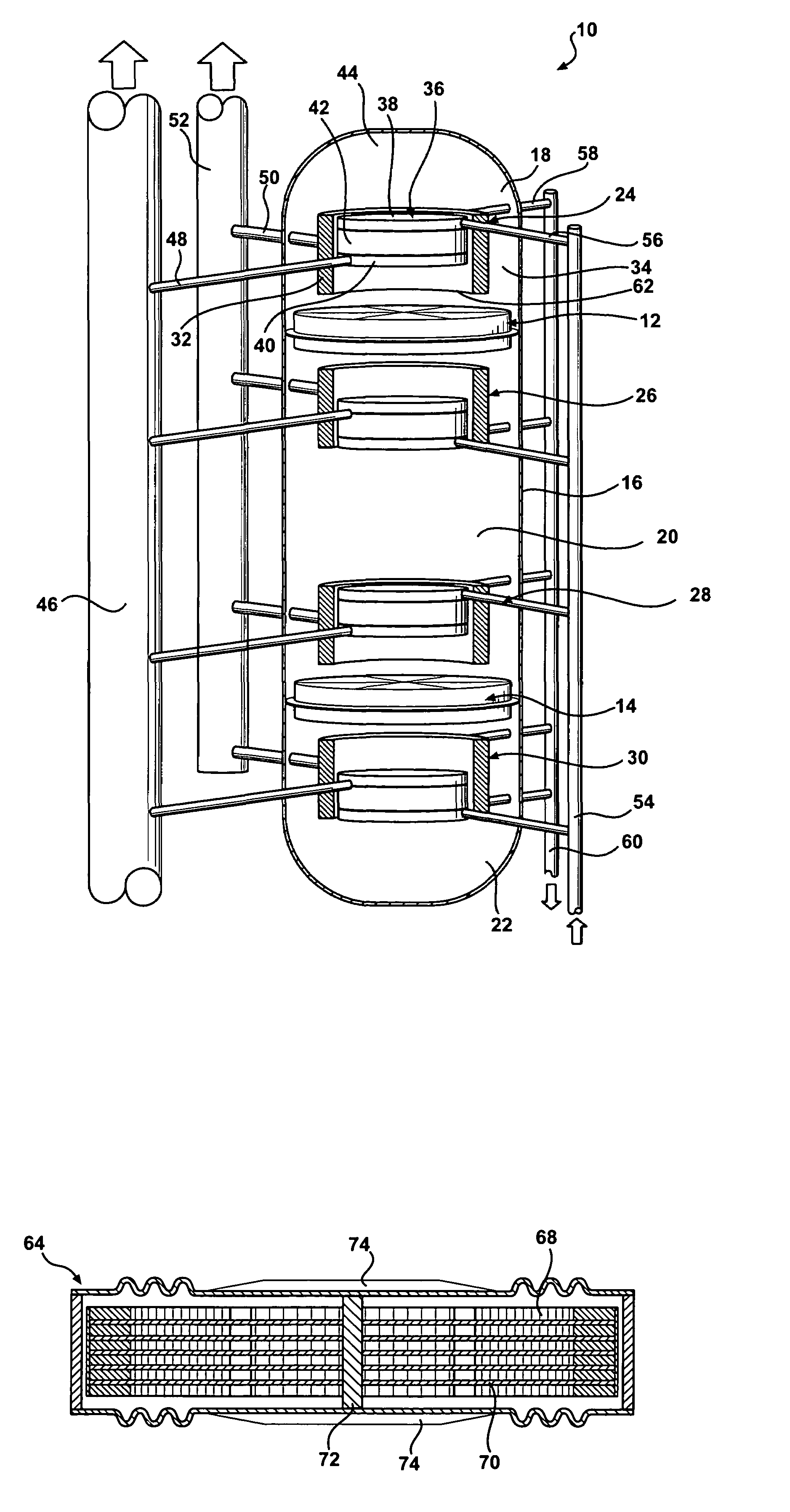
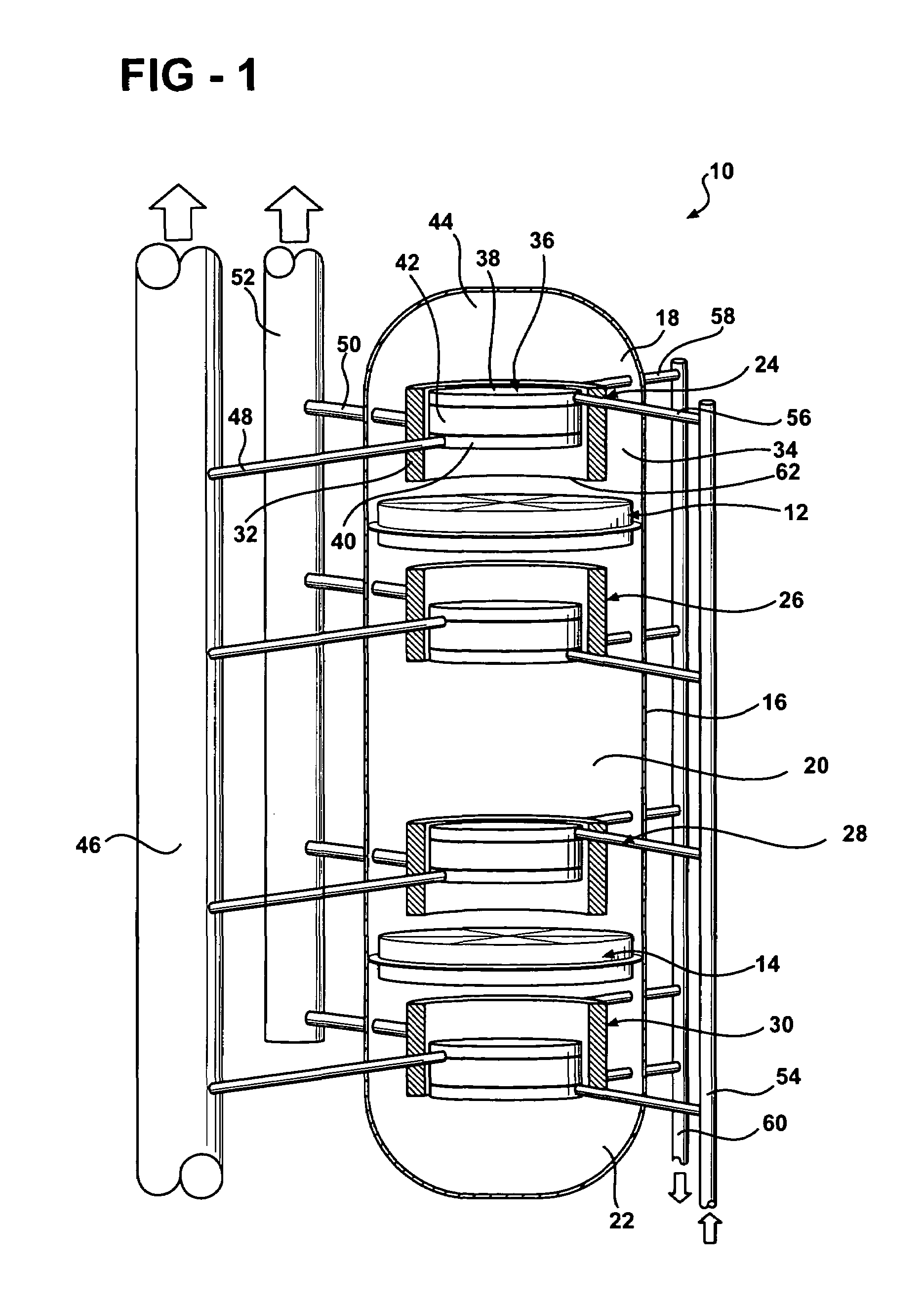
[0018]The present invention is a thermoacoustic-piezoelectric electrical power generator that uses the heat driven pressure and volume oscillations of thermoacoustic prime movers to power piezoelectric alternators. Refrigeration stages may be added to the generator as well. A first embodiment of the present invention is a thermoacoustic generator, including a housing containing a working volume of gas with a pressure. A thermoacoustic core is supported in the housing and includes a first heat exchanger and a second heat exchanger. The thermoacoustic core is operable to introduce acoustical power into the housing, thereby oscillating the pressure of the gas at a frequency. A piezoelectric alternator is supported in the housing and has a face that is movable when acted on by acoustical power. The alternator further includes a portion of piezoelectric material operable to produce electrical power when acted on by a stress. The portion of piezoelectric material is in mechanical communication with the movable face, such that the movement of the face stresses the portion of piezoelectric material so as to produce electrical power. The alternator has a moving mass that serves as a substantial portion of the resonating mass inside the housing. This provides a pressure oscillation frequency in the housing that is substantially lower than for a similar system with a rigid member replacing the alternator. In a preferred version of the first embodiment, the movable face of the alternator substantially blocks the passage of gas.
[0024]In yet another version of the first embodiment, the piezoelectric alternator may further include at least one spring in series with a portion of piezoelectric material, so as to alter the stiffness of the piezoelectric alternator.

Problems solved by technology

Although Stirling engines have been under development for almost 200 years, their mechanical complexity has historically limited their commercial viability.
Stirling engines with high power density typically have internal pressures in excess of 20 atmospheres, creating problems with the pressure vessel penetrations and sliding seals necessary for connecting rods and moving pistons.
The mass of the moving parts also limits the operating frequency of the engine to the detriment of the engine's power density.
However, the problems associated with internal sliding piston seals and the limits brought on by large piston masses remain.
However, they suffer from poor efficiency associated with the necessarily poor heat transfer between the gas and the stack.
Raising the operating frequency is limited by the ability of the heat exchangers to function properly when their effective size is limited by the shorter acoustic displacements that result at higher frequencies, by the parasitic thermal conduction between hot and cold regions of the engine which will be closer together as the frequency is increased, and by the moving mass of any transducers used to exchange electrical power with the engine.
Electrodynamic alternators, however, have the disadvantage that their moving mass tends to be large.
This is not generally a problem at low operating frequencies, where it is more important that the alternator have a large stroke to roughly match the large displacement amplitude of the sound, but the large moving mass limits the use of electrodynamic transducers at high frequencies.
Some of these applications appear to be impractical.
However, like many traditional acoustic transducers, it presents to the resonator a very high impedance, and it has a very limited available stroke, factors which are associated with the high mechanical stiffness and limited mechanical strain of a raw piece of piezoelectric ceramic.
This Los Alamos configuration of a piezoelectric alternator cannot take the space saving advantage of using the alternator as a resonating mass that may substitute for much of the gaseous mass of the acoustic resonator.
With its high impedance and large mass of coupling fluids, it is unsuitable for use with thermoacoustic engines.

Method used


Image

  • Thermoacoustic piezoelectric generator
  • Thermoacoustic piezoelectric generator
  • Thermoacoustic piezoelectric generator

Examples


example 1

Ring Alternator

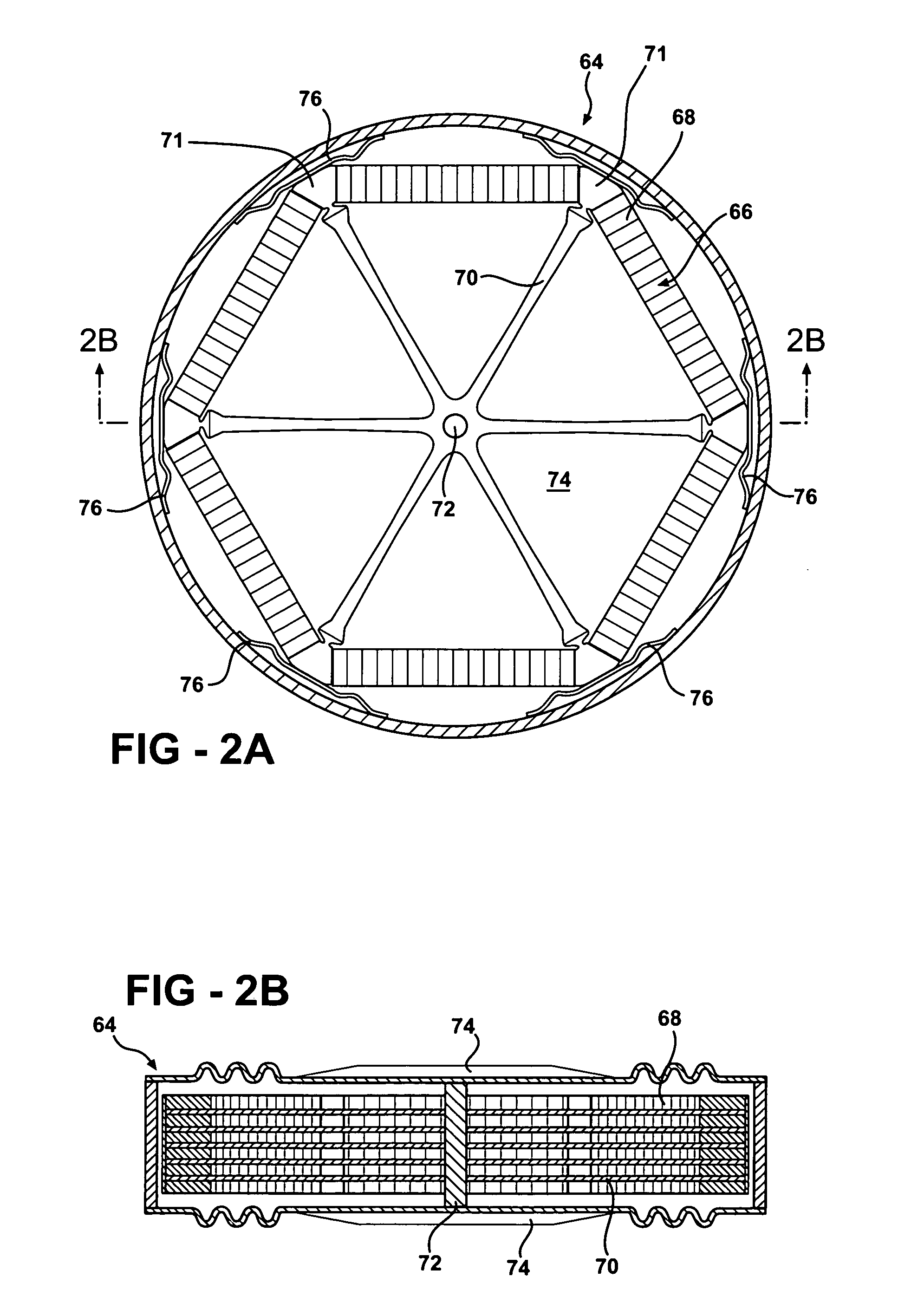
[0072]A first preferred embodiment of the alternator is the quadratically driven piezoelectric ring transducer or alternator 64 of FIGS. 2A and 2B. The transducer consists of a ring 66 of piezoelectric material 68, such as the poled ceramic lead-zirconate-titanate PZT, attached to sets of flexible radial spokes 70 via keystone-like supports 71. Other piezoelectric materials may be used, as will be clear to those of skill in the art. The ring 66 can be circular or polygonal; a hexagon with six sets of spokes is shown in the figure. Other shapes are also possible. The ring 66 may also be referred to as a perimeter member that includes a portion of piezoelectric material. The member is configured such that compression of the perimeter member causes compression of the piezoelectric portion. In the illustrated embodiment, the piezoelectric material forms substantially all of the straight segments extending between the supports 71, located at the intersection zones between ...

example 2

Bimorph Alternator

[0078]A second embodiment of a piezoelectric alternator 78 that presents a mass impedance to the thermoacoustic engines, thus reducing the necessary size of the pressure-vessel / acoustic-resonator, is shown in the two cutaway views of FIGS. 4A and 4B, drawn generally to scale. For definiteness, the figures show the core of a 2.0 kW thermoacoustic-Stirling piezoelectric generator. In one version, the steel pressure-vessel / acoustic-resonator 80 is 36 cm (14″) long, 15 cm (6″) in diameter at the ends, and bulges to 23 cm (9″) diameter at the center. The resonator is filled with 10 atmosphere (150 psi) of helium gas. The walls of the resonator are 0.65 mm thick in the small diameter regions and 1.0 mm thick near the center to perform safely as a pressure vessel. Other dimensions, working fluids and pressures, of course, are possible.

[0079]Two flexible diaphragms 82 and 84 are located in the center of the resonator. In this embodiment, the diaphragms form the movable fac...

example 3

Ring Alternator with Spokes and Azimuthal Springs

[0093]Azimuthal springs may be added to the embodiment of the alternator in FIGS. 2A and 2B, as shown in FIG. 5, to lower the ring resonant frequency in the generator to twice the acoustic frequency. This embodiment shares with the embodiment of FIGS. 2A and 2B two force amplifying mechanisms for matching the mechanical impedance of the transducer to that of the engine: the conversion of axial force on the hub 104 into radial tension on the spokes 105, and the conversion of tension in the spokes to compression of the ring 106.

[0094]The alternator 103 of FIG. 5 may be used in place of the alternator of FIGS. 2A and 2B. As with the alternator of FIGS. 2A and 2B, the alternator 103 includes a ring 106 of piezoelectric material that forms a perimeter member. The ring includes stacks of piezoelectric material extending between supports 108. Azimuthal springs 107 are placed between the stack of piezoelectric material and each support 108. T...


PUM


Abstract

A thermoacoustic generator includes a housing with a thermoacoustic core supported in the housing. The core is operable to introduce acoustical power into the housing to thereby oscillate the pressure of the gas in the housing at a frequency. A piezoelectric alternator is also supported in the housing and has a face that is movable when acted on by the acoustical power. The alternator includes a portion of piezoelectric material operable to produce electrical power when acted upon by a stress. The piezoelectric material is in mechanical communication with the movable face so that movement of the face stresses the piezoelectric material. The alternator has a moving mass that serves as a substantial portion of the resonating mass inside the housing, thereby providing a pressure oscillation frequency in the housing substantially lower than for a similar system with a rigid member replacing the alternator.

Description

RELATED APPLICATIONS[0001]This application claims priority of U.S. Provisional Patent Application 60 / 459,541, filed Mar. 31, 2003, which is incorporated herein by reference.GOVERNMENT SPONSORSHIP[0002]This work was supported by the Office of Naval Research grant number N00014-98-1-0212 and N00014-03-0652. Accordingly the US government may have certain rights in this invention.FIELD OF THE INVENTION[0003]The invention relates to the field of electrical power generation from heat using oscillatory linear motion alternators.BACKGROUND OF THE INVENTION[0004]Oscillatory heat engines such as thermoacoustic engines or Stirling engines may be used for refrigerators or heat pumps, where the energy of gas pressure and volume oscillations is converted into the movement of heat into the engine at low temperatures and out of the engine at high temperatures. Oscillatory heat engines may also be used as prime movers, where heat flow into the engine at high temperatures and out of the engine at low...

Claims


Application Information

Patent Timeline
Patent Type & Authority Patents(United States)
IPC IPC(8): H01L41/00F25B9/00H02N2/00F01B9/00F01B29/10H01LH01L41/08H01L41/113
CPCH02N2/18H01L41/113H10N30/30
Inventor KEOLIAN, ROBERT M.BASTYR, KEVIN J.
Owner PENN STATE RES FOUND
Learn More