Circuit Device, Oscillator, Electronic Apparatus, And Vehicle

Active Publication Date: 2019-06-20
SEIKO EPSON CORP
View PDF0 Cites 2 Cited by
  • Summary
  • Abstract
  • Description
  • Claims
  • Application Information

AI Technical Summary

Benefits of technology

The invention is related to a circuit that controls the frequency of oscillation in an electronic device. The circuit includes two variable capacitance capacitors, each controlled by a separate voltage signal. By controlling the potential difference between the two signals, the circuit reduces fluctuations in the oscillation frequency. This allows for a more stable and linear change in frequency with respect to voltage. The circuit also includes a coupling node and a capacitor to ensure that the same bias voltage is supplied to both capacitors. Overall, the circuit improves the accuracy and stability of the electronic device's oscillation frequency.

Problems solved by technology

In a case where this control voltage fluctuates due to noise or the like, frequency drift may occur due to the fluctuations, and the accuracy of the oscillation frequency may decrease.

Method used


Image

  • Circuit Device, Oscillator, Electronic Apparatus, And Vehicle
  • Circuit Device, Oscillator, Electronic Apparatus, And Vehicle
  • Circuit Device, Oscillator, Electronic Apparatus, And Vehicle

Examples


Embodiment Construction

[0041]Hereinafter, preferred embodiments of the invention will be described in detail. The present embodiment described below does not unduly limit the contents of the invention described in the appended claims, and not all of the configurations described in the embodiment are necessarily indispensable as a solving means of the invention.

1. First Configuration Example of Circuit Device

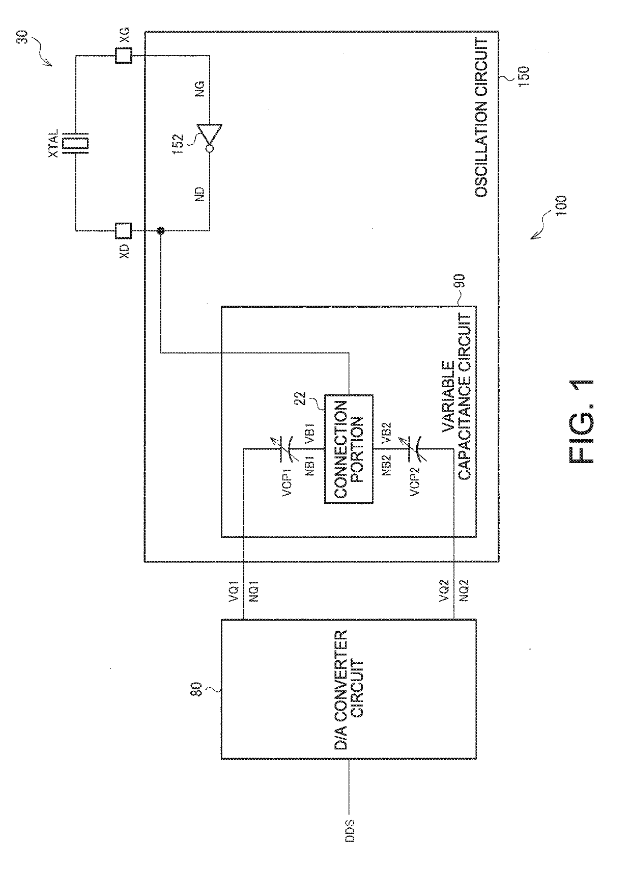
[0042]FIG. 1 is a first configuration example of a circuit device 100. The circuit device 100 includes an oscillation circuit 150 and a D / A converter circuit 80. In addition, the circuit device 100 includes a terminal XD (pad, first resonator terminal) to which one end of a resonator XTAL is connected and a terminal XG (pad, second resonator terminal) to which the other end of the resonator XTAL is connected.

[0043]The D / A converter circuit 80 performs D / A conversion on frequency control data DDS and outputs D / A converted voltage signals of differential signals corresponding to the frequency control dat...


PUM


Abstract

A circuit device includes a drive circuit driving a resonator, an oscillation circuit having the resonator and a variable capacitance circuit coupled to an oscillation loop including the drive circuit, and a D / A converter circuit that performs D / A conversion on frequency control data and outputs a first voltage signal and a second voltage signal which are differential signals. The variable capacitance circuit includes a first variable capacitance capacitor, to one end of which the first voltage signal is input and, to the other end of which a first bias voltage is input and a second variable capacitance capacitor, to one end of which the second voltage signal is input and, to the other end of which a second bias voltage is input.

Description

BACKGROUND1. Technical Field[0001]The present invention relates to a circuit device, an oscillator, an electronic apparatus, a vehicle, and the like.2. Related Art[0002]An oscillator that performs temperature compensation processing of an oscillation frequency by using temperature detection data which is a result of A / D conversion of a temperature detection voltage (analog signal) from a temperature sensor and reduces fluctuations of the oscillation frequency when a temperature changes is known. For example, a temperature compensated oscillator called temperature compensated crystal oscillator (TCXO) is known. The TCXO is used as a reference signal source or the like in, for example, a mobile communication terminal, a GPS related device, a wearable device, an in-vehicle device or the like.[0003]In such an oscillator such as a TCXO, high frequency stability is desired. For example, JP-A-2017-85535 discloses a technique of changing the frequency control data to be output to an oscilla...

Claims


Application Information

Patent Timeline
IPC IPC(8): H03B5/30B81B7/00H03L1/04H03L7/093H03L7/099H03M1/46
CPCH03B5/30B81B7/008H03L1/04H03L7/093H03L7/099H03M1/46B81B2207/03H03B2200/0062H03L1/00H03L1/022H03M3/50H03B5/366H03B2201/0208H03L1/027
Inventor HANEDA, HIDEOTSUTSUMI, AKIO
Owner SEIKO EPSON CORP
Why Eureka
Try Eureka