
Water wall boiler for air and oxygen fired Claus sulfur recovery units

a technology of claus reaction furnace and water wall boiler, which is applied in the direction of sulfur preparation/purification, separation processes, energy input, etc., can solve the problems of increasing the temperature reducing the efficiency of the claus reaction furnace, and limited conversion in the catalytic bed. achieve the effect of reducing the heat release rate and heat flux, and increasing the effective surface area

Inactive Publication Date: 2006-06-27
WORLEYPARSONS GROUP
View PDF19 Cites 6 Cited by
  • Summary
  • Abstract
  • Description
  • Claims
  • Application Information

AI Technical Summary

Benefits of technology

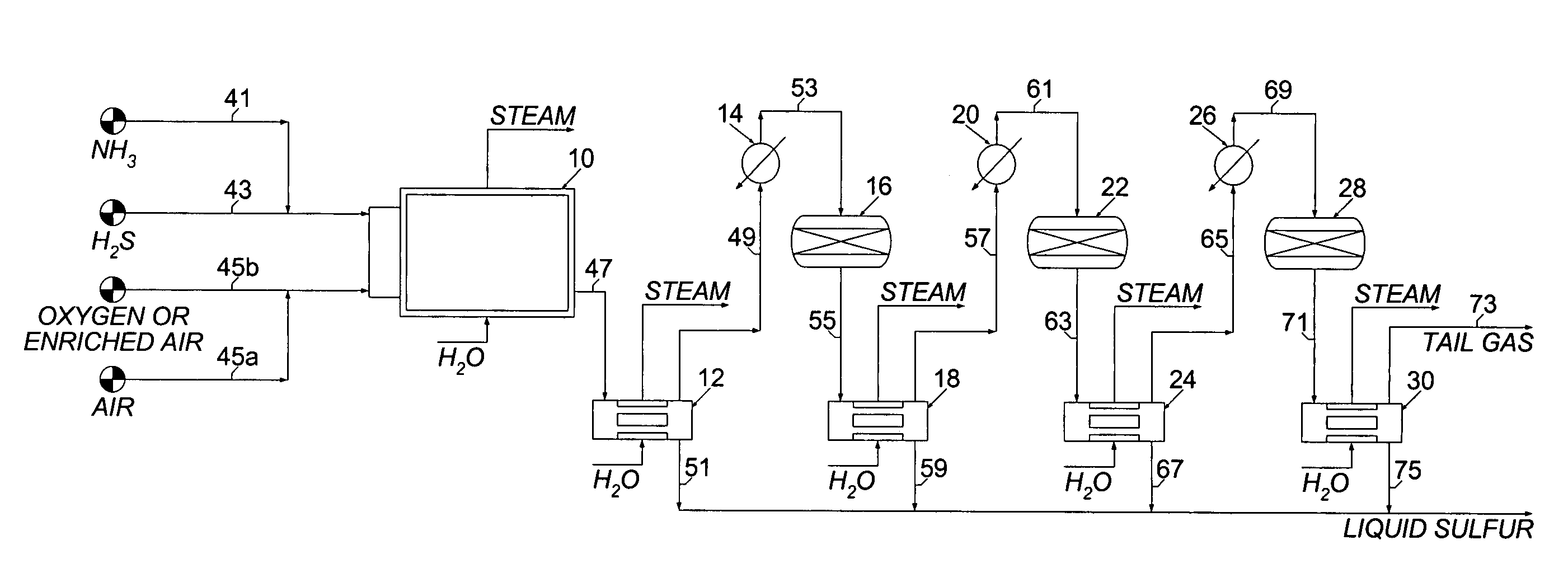
"The present invention is about a new method for carrying out the thermal combustion step of the modified Claus process using a water-wall boiler. This boiler replaces the conventional refractory-lined reaction furnace and waste heat boiler used in the process. The water-wall boiler is designed to withstand high temperatures and can be used for all levels of oxygen enrichment. The boiler has a radiant section using water-wall tubes and a refractory-lined section to hold the temperature at a desired level for completion of the conversion reactions. The combustion products are cooled to a safe temperature in the convection section of the boiler. The water-wall boiler eliminates problems associated with refractory maintenance and has lower furnace area heat release rates and heat fluxes. This invention can be used for new Claus plants or for the revamp of existing Claus units for air and / or oxygen operation."

Problems solved by technology

As thermodynamics favor reaction at reduced temperatures, only a limited amount of conversion is achieved in each catalytic bed.
The nitrogen does not benefit the process and actually results in having to use larger and more expensive equipment in the Claus sulfur plant.
However, this results in higher temperatures in the Claus reaction furnace.
Such refractory linings are undesirable because of the time and expense required to install the lining, the time required to heat the lining during start-up of the unit, the time required to cool the lining during shutdown of the unit, and the expense and lost on-stream time and sulfur production caused by damage to or failure of the lining, which requires that the unit be shut down for repairs.

Method used


Image

  • Water wall boiler for air and oxygen fired Claus sulfur recovery units
  • Water wall boiler for air and oxygen fired Claus sulfur recovery units

Examples


Embodiment Construction

[0019]Oil and gas-fired packaged steam generators are widely used in chemical plants, refineries and cogeneration systems. Custom-designed steam generators for modified Claus sulfur plants are considered where the feed gas is a hydrogen sulfide rich feed gas stream, is increased by combusting hydrogen sulfide in one stage with an oxidant which is an oxygen rich gas stream comprised of air, oxygen or a mixture of air and oxygen.

[0020]The boiler is designed as a furnace to achieve the proper combustion with minimum pressure drop by adjusting the boiler height, tube spacing, tube counts, high efficiency, low operating cost, proper material selection and without flame impingement concerns. The water-wall boiler replaces the conventional refractory-lined reaction furnace and waste heat boiler.

[0021]The water-wall boiler can be designed with partial or no refractory depending on the application and the maximum combustion temperature for any Claus unit air operation or any combination of a...


PUM

PropertyMeasurementUnit
pressureaaaaaaaaaa
pressureaaaaaaaaaa
pressureaaaaaaaaaa

Abstract

The thermal combustion step of the modified Claus process is carried out in a water-wall boiler instead of a refractory-lined reaction furnace. The water-wall boiler replaces the conventional refractory-lined furnace and waste heat boiler when air, oxygen, or oxygen-enriched air is used as the oxidant. The acid gas combustion may be hydrogen sulfide-rich or hydrogen sulfide-lean with or without contaminants such as hydrocarbons and ammonia. Thermal combustion is performed in a single stage, without a recycle, for all levels of oxygen enrichment.

Description

CROSS REFERENCE TO RELATED APPLICATIONS[0001]This application claims the benefit under 35 U.S.C. 119(e) of U.S. Provisional Patent Application No. 60 / 482,908 filed Jun. 25, 2003STATEMENT REGARDING FEDERALLY SPONSORED RESEARCH OR DEVELOPMENT[0002]Not ApplicableREFERENCE TO SEQUENCE LISTING[0003]Not ApplicableREFERENCE TO A TABLE[0004]Not ApplicableREFERENCE TO A COMPUTER PROGRAM LISTING COMPACT DISK APPENDIX[0005]Not ApplicableBACKGROUND OF THE INVENTION[0006]The present invention relates to a process for recovering sulfur from hydrogen sulfide containing gases.[0007]In the conventional sulfur plant, hydrogen sulfide rich gas are processed through the reaction furnace (combustion chamber) followed by the waste heat boiler. The water wall boiler replaces the reaction furnace (combustion chamber) and the waste heat boiler, while the remaining of the equipment stay the same.[0008]It is known that the sulfur present in refinery crudes including natural gas exists as hydrogen sulfide or, ...

Claims


Application Information

Patent Timeline
Patent Type & Authority Patents(United States)
IPC IPC(8): C01B17/02B01D53/52C01B17/04
CPCC01B17/0413Y02P20/129
Inventor RAMESHNI, MAHIN
Owner WORLEYPARSONS GROUP
Learn More