Cooling system for electronic equipment

Inactive Publication Date: 2017-09-21
EXASCALER
View PDF12 Cites 14 Cited by
  • Summary
  • Abstract
  • Description
  • Claims
  • Application Information

AI Technical Summary

Benefits of technology

The invention is a cooling system that uses a perfluorinated compound as the main component. This compound has excellent features such as high electric insulating properties, high heat transfer capacity, inertness, and stability. The cooling system can reduce evaporative loss of the liquid coolant and achieve efficient cooling of electronic devices in a small volume. It can also be adapted to cool multiple electronic devices in a sealed cooling bath. The cooling system is designed to prevent potential hazards associated with the boiling of the liquid coolant, such as the generation of harmful fluorinated compounds, and to ensure stable operation. The cooling system can deliver uniform cooling performance for the individual electronic devices and achieve continuous and stable operation.

Problems solved by technology

One of the largest issues deciding the performance limit of recent supercomputers is power consumption.
However, a synthetic oil having high viscosity is used as a liquid coolant and hence, it is quite difficult to completely remove the adherent oil from electronic devices extracted from an oil immersion rack.
This leads to an extremely complicated maintenance work for the electronic devices (specifically, adjustment, inspection, repair, part replacement, and expansion.
Further, it is reported that the synthetic oil used in the cooling system may leak as corroding packing and the like constituting the cooling system in the short term, so as to adversely affect the operation of the cooling system.

Method used


Image

  • Cooling system for electronic equipment
  • Cooling system for electronic equipment
  • Cooling system for electronic equipment

Examples


Embodiment Construction

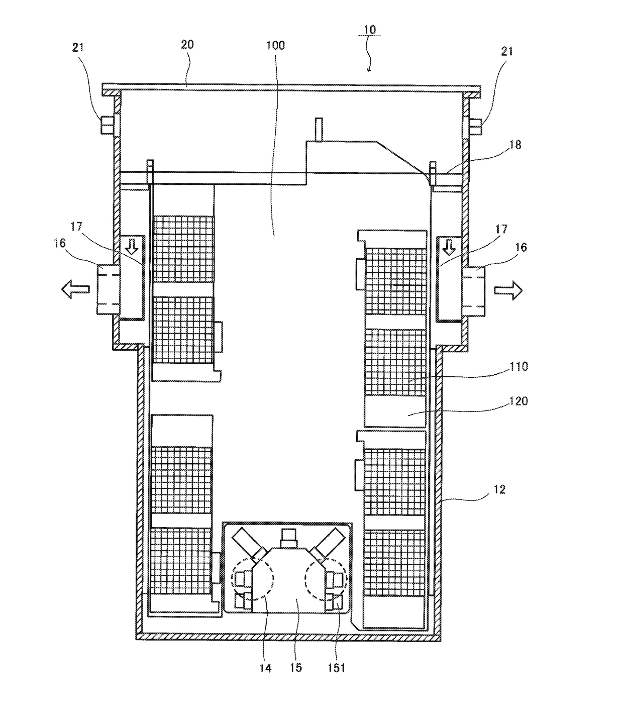
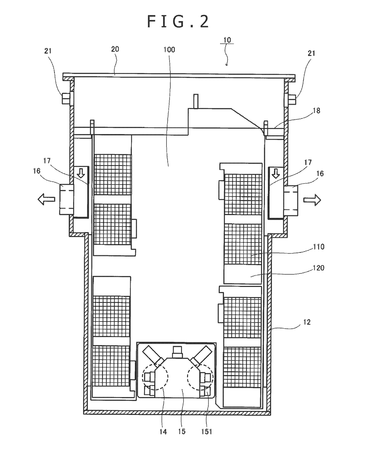
[0031]A cooling system according to a preferred embodiment of the invention will hereinbelow be described in detail with reference to the accompanying drawings. The description of the embodiment is made on an example where 8 units of electronic devices in total are densely accommodated in a cooling bath. One unit of electronic device has a structure where 4 processor boards are arranged on one surface thereof, the processor board mounted with a plurality of processors. This example is intended for illustrative purpose and the number of processors per board or the type of the processor is arbitrary. Further, the number of electronic device units is arbitrary as long as two or more electronic device units are accommodated. Such number and type do not limit the configuration of the electronic device according to the invention.

[0032]Referring to FIG. 1 and FIG. 2, a cooling system 10 includes a cooling bath 12. The cooling bath 12 is provided with two inlet ports 14 at each of a left-si...


PUM


Abstract

A cooling system is adapted for reduction of evaporative loss of a liquid coolant and for efficient cooling of plural electronic devices densely accommodated in a cooling bath of a small volume. A cooling system accommodates plural electronic devices in an open space of a cooling bath provided with an inlet port and an outlet port for a liquid coolant. The cooling system is configured to directly cool the electronic devices by immersion of the electronic devices in the liquid coolant circulated in the open space. The liquid coolant contains a perfluorinated compound as a main component. The liquid coolant is adapted to exhibit a liquid weight loss percentage of 1.5% or less as determined by allowing 10 ml of the liquid coolant in a 10-ml measuring cylinder (opening diameter: 11.5 mm) to spontaneously evaporate under normal environment at a room temperature of 25° C. for 100 hours.

Description

TECHNICAL FIELD[0001]The present invention relates to a cooling system for electronic equipment. Particularly, the invention relates to a system for efficiently cooling electronic equipment such as supercomputer or electronic equipment at a data center which is required of ultrahigh performance operation and generates a large amount of heat per se.BACKGROUND ART[0002]One of the largest issues deciding the performance limit of recent supercomputers is power consumption. The importance of studies concerning thrifty power consumption of the supercomputer has already received wide recognition. Namely, speed performance per unit power consumption (Flops / W) is regarded as one evaluation index of supercomputer. It is reported that about 45% of the total power consumption of the data center is consumed for cooling. There is a growing demand for reducing the power consumption by increasing cooling efficiency.[0003]Conventionally, an air cooling system and a liquid cooling system are used for...

Claims


Application Information

Patent Timeline
IPC IPC(8): H05K7/20H01L23/44
CPCH05K7/20772H05K7/20236H05K7/20272H01L23/44H05K7/20836H01L23/473H01L2924/0002C09K5/10G06F1/20G06F2200/201H05K7/20781H01L2924/00
Inventor SAITO, MOTOAKI
Owner EXASCALER
Why Eureka
Try Eureka