
Method for efficiently recovering carbon dioxide in gas

a carbon dioxide and gas recovery technology, applied in the field of carbon dioxide recovery, can solve the problems of high energy consumption, difficult to separate the absorbed carbon dioxide, and high energy consumption, and achieve excellent excellent carbon dioxide separation performance, and good balance between carbon dioxide absorption performance and carbon dioxide separation performan

Active Publication Date: 2010-05-27
RES INST OF INNOVATIVE TECH FOR THE EARTH
View PDF7 Cites 15 Cited by
  • Summary
  • Abstract
  • Description
  • Claims
  • Application Information

AI Technical Summary

Benefits of technology

[0021]The method for separating and recovering carbon dioxide using the aqueous solution for CO2 recovery of the present invention has, in addition to excellent carbon dioxide absorption performance, excellent carbon dioxide separation performance compared to methods using a known aqueous solution for CO2 recovery, and has a good balance between carbon dioxide absorption performance and carbon dioxide separation performance. Accordingly, an extremely large amount of carbon dioxide can be recovered per cycle of the absorption and separation steps.
[0022]Furthermore, the heat of the absorption reaction of carbon dioxide is low. Therefore, carbon dioxide can be separated at low temperatures to recover high-purity carbon dioxide. Separation of carbon dioxide at low temperatures results in reduction of the energy required to raise the water temperature of the amine aqueous solution, thus providing a great energy-saving effect in the separation step.
[0023]As described above, the present invention realizes downsizing of carbon dioxide absorption towers, carbon dioxide separation towers, and equipment associated with such towers; and also reduces the amount of liquid circulated to thereby reduce construction cost as well as energy loss, which leads to energy saving in the separation step. Therefore, the present invention is of great industrial value.

Problems solved by technology

However, the use of such an aqueous alkanolamine solution as an absorbing solution requires either the use of an expensive anti-corrosion steel as the equipment material or the reduction of the amine concentration in the absorbing solution, because the solution is highly corrosive to the equipment material.
Furthermore, because it is difficult to separate the absorbed carbon dioxide, the solution must be heated at a high separation temperature of 120° C. to separate and recover carbon dioxide.
Another disadvantage is the high energy, i.e., 20 kcal / mol CO2, required to separate carbon dioxide from the absorbing solution.
In an age when the reduction of carbon dioxide emissions, energy saving, and resource saving are desired, this high energy consumption is a major impediment to the realization of a carbon dioxide absorption and recovery system.
Although many attempts have been made to increase the efficiency of the step for absorbing carbon dioxide into an aqueous solution as described above, either carbon dioxide separation efficiency was not considered, or the only available methods were insufficient in terms of the amount of CO2 separated or the separation rate.
Therefore, the balance between CO2 absorption and CO2 separation was poor in known methods for recovering carbon dioxide, which resulted in low carbon dioxide recovery efficiency.
Another important issue is reduction of the heat of the carbon dioxide absorption reaction, i.e., the heat used to separate carbon dioxide, in order to attain CO2 recovery at low cost.

Method used


Image

  • Method for efficiently recovering carbon dioxide in gas
  • Method for efficiently recovering carbon dioxide in gas
  • Method for efficiently recovering carbon dioxide in gas

Examples


case 1

, in which Other Amine is a Main Component, and IPAE is an Accessory Component

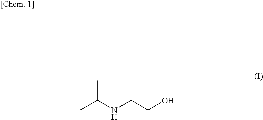
[0074]The following Examples show cases in which an aqueous solution of other amine is modified by replacing part of other amine with IPAE, or adding a small amount of IPAE as an additive.

example 1

[0075]A glass gas absorption bottle was immersed into a constant temperature water bath whose liquid temperature was set to 40° C. This bottle was filled with 50 ml of an aqueous solution containing 10 wt. % of IPAE and 20 wt. % of PZ. A mixed gas containing 20 volume % of carbon dioxide and 80 volume % of N2 was dispersed as bubbles into this solution at a rate of 0.7 l / min through a glass filter with a pore size of 100 μm and a diameter of 13 mm at atmospheric pressure to cause absorption.

[0076]The CO2 concentration in the gas was continuously measured at the inlet and outlet of the absorbing solution using an infrared carbon dioxide meter (HORIBA GAS ANALYZER VA-3000). The amount of CO2 absorbed was determined from the difference between the CO2 flow rate at the inlet and the CO2 flow rate at the outlet. When necessary, the amount of inorganic carbon in the aqueous solution was measured using a total organic carbon meter for gas chromatography (SHIMADZU TOC-VCSH), and compared wi...

examples 2 and 3

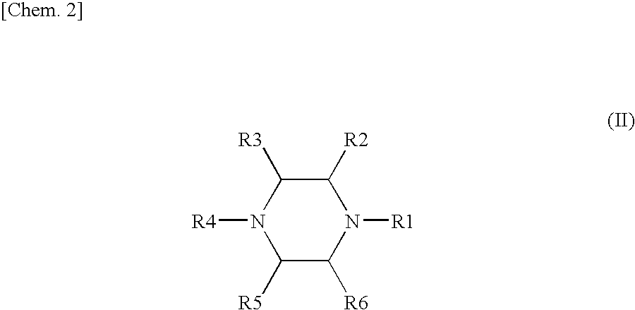
[0078]Using aqueous solutions containing IPAE, piperazine (PZ), 2-amino-2-methyl-1-propanol (AMP), and N-methyldiethanolamine (MDEA) in the concentrations shown in Table 1, the amount of CO2 absorbed to saturation, the absorption rate, the amount of CO2 separated, and the separation rate were measured using the same equipment and conditions as in Example 1. Table 1 shows the results.


PUM

PropertyMeasurementUnit
Temperatureaaaaaaaaaa

Abstract

Disclosed is a method for recovering carbon dioxide from a gas containing carbon dioxide, comprising the step (1) of bringing a gas containing carbon dioxide into contact with an aqueous solution containing 2-isopropylaminoethanol and at least one substance selected from the group consisting of piperazines and alkanolamines to absorb carbon dioxide into the aqueous solution; and the step (2) of heating the aqueous solution containing carbon dioxide absorbed therein, which is obtained in the step (1), to separate and recover carbon dioxide from the solution.

Description

TECHNICAL FIELD[0001]The present invention relates to a method for recovering carbon dioxide (CO2) from a gas containing carbon dioxide, which comprises absorbing carbon dioxide using an aqueous solution for CO2 recovery, and subsequently separating and recovering carbon dioxide from the aqueous solution.BACKGROUND ART[0002]In recent years, frequent disasters and climate change that are probably caused by global warming have had a tremendous influence on agricultural production, living conditions, energy consumption, etc. This global warming is considered to be caused by an increase in the presence of greenhouse gases such as carbon dioxide, methane, nitrous oxide, and CFCs in the atmosphere, which is associated with an increase in human activity. The main gas among the greenhouse gases is atmospheric carbon dioxide. To prevent global warming, the Global Warming Prevention Conference (COP3) was held in Kyoto in December, 1997. The Kyoto Protocol, which was adopted at the Global Warm...

Claims


Application Information

Patent Timeline
IPC IPC(8): B01D53/14C01B32/50
CPCB01D53/1475B01D53/1493Y02C10/06C01B31/20Y02C10/04B01D2257/504C01B32/50Y02C20/40Y02P20/151
Inventor SHIMIZU, SHINKICHICHOWDHURY, FIROZ ALAMOKABE, HIROMICHIGOTO, KAZUYA
Owner RES INST OF INNOVATIVE TECH FOR THE EARTH
Learn More