
Method of manufacturing multilayer material for plain bearing

Inactive Publication Date: 2006-06-27
DAIDO METAL CO INC
View PDF3 Cites 7 Cited by
  • Summary
  • Abstract
  • Description
  • Claims
  • Application Information

AI Technical Summary

Benefits of technology

[0008]Therefore, an object of the present invention is to provide a method of manufacturing a multilayer material which has a fine structure and a high strength.
[0021]Metal powder may be deoxidized before and after spread onto the back metal. When metal powder is deoxidized after having been spread onto the back metal, laser beam can be irradiated onto the metal power immediately after deoxidization. Consequently, oxides can be prevented from being reproduced.
[0022]In the above-described method, the metal powder is sprinkled on the back metal and melted by laser beam. Thereafter, the melted metal powder is quenched, whereby a bimetal is produced. This method requires no equipment both for the primary and secondary sintering and rolling equipment all of which equipment the conventional sintering method requires. Furthermore, this method requires no large-scaled equipment for melting a metal nor large-scaled cooling system for cooling a large amount of molten metal poured on the steel plate as in the conventional continuous casting method. Consequently, the production line for the multilayer material can be shortened. Moreover, part of the metal powder on the back metal is rapidly melted and cooled such that the structure of the bearing alloy layer can be fine.
[0023]A copper alloy is one of materials having finest characteristics and has a good wettability and a high bonding performance with respect to the steel back metal. However, the copper alloy is inferior in light absorption. In view of these characteristics of the copper alloy, a semiconductor laser is preferred. Laser beam generated by the semiconductor laser has a wavelength ranging from 0.8 to 1.1 μm. Since the wavelength exhibits a high light absorption rate for copper alloy, the method of the present invention can desirably be carried out when the copper alloy and the semiconductor laser are combined together.
[0026]The multilayer material manufactured by the method of the present invention includes a metal plate having a dendritic structure extending approximately perpendicularly to the surface of the back metal. As a result, when a plain bearing is made of the multilayer material manufactured by the method of the invention, the trunk of the dendritic structure corresponds with a load direction of a counter material and accordingly, the trunk serves as a column supporting the load. Consequently, the strength and fatigue resistance of the plain bearing can be improved.
[0027]Furthermore, the dendritic structure of the metal plate has a crystal grain size equal to or smaller than 0.02 mm at a cut surface thereof parallel to a surface of the back metal and / or a dendritic arm spacing equal to or smaller than 0.02 mm at a cut surface thereof vertical to the surface of the back metal. Consequently, when a sliding bearing is manufactured of the multilayer material, the anti-seizure property and fatigue resistance of the plain bearing can be improved.

Problems solved by technology

Moreover, the local heating has only a small thermal effect on the other part.

Method used


Image

  • Method of manufacturing multilayer material for plain bearing
  • Method of manufacturing multilayer material for plain bearing
  • Method of manufacturing multilayer material for plain bearing

Examples


Embodiment Construction

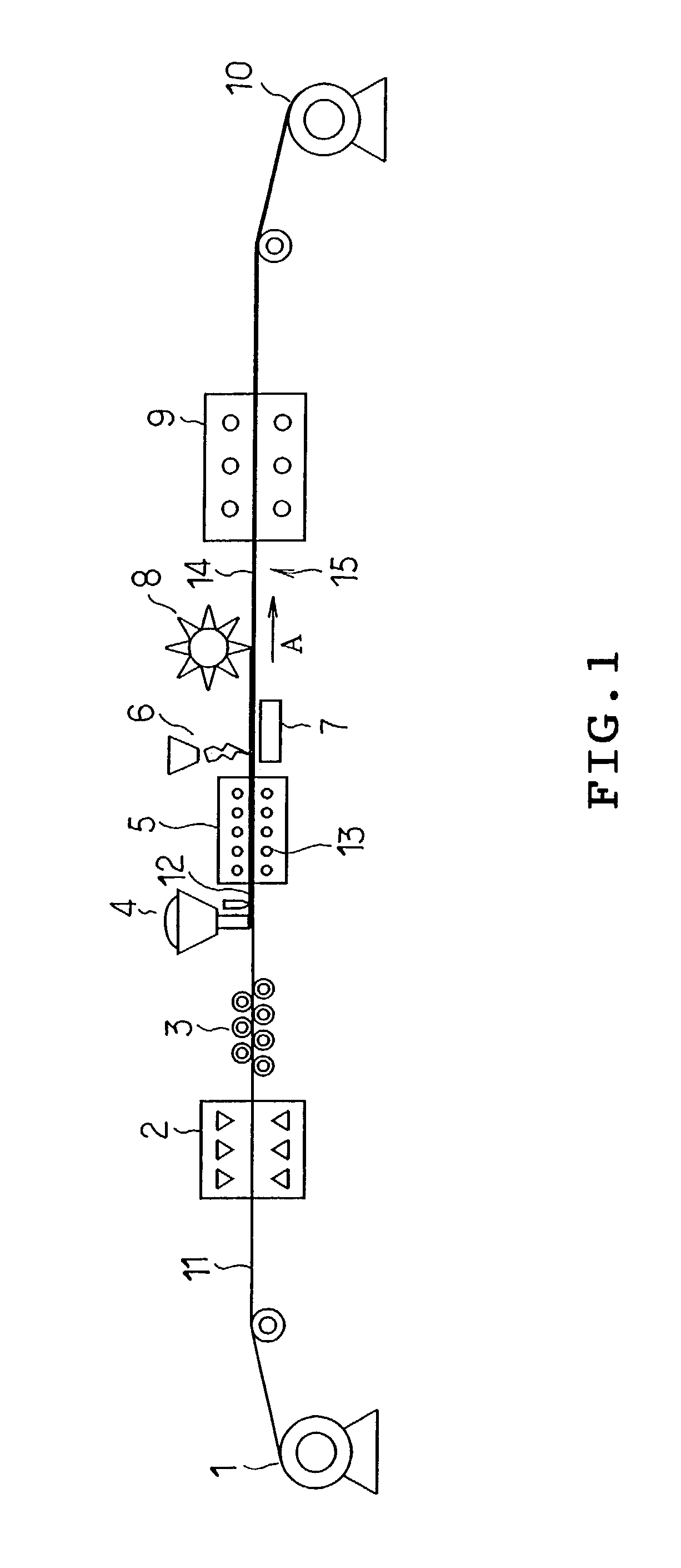
[0044]One embodiment of the present invention will be described with reference to the accompanying drawings. The invention is applied to a multilayer material for a bearing which is composed by bonding a copper bearing alloy to a steel plate. Referring to FIG. 1, manufacturing equipment for the multilayer material is schematically shown. The equipment includes an uncoiler 1, cleaning apparatus 2, leveler 3, powder spreader 4, deoxidizing furnace 5, laser apparatus 6, cooling apparatus 7, milling 8, annealing furnace 9 and coiler 10 arranged in this sequence.

[0045]The uncoiler 1 uncoils a coiled band steel 11 serving as a back metal. The band steel 11 drawn out of the uncoiler 1 is cleaned by the cleaning apparatus 2 and thereafter, curl of the band steel 11 is cured by the leveler 3. The powder spreader 4 is provided for spreading a copper alloy powder 12 onto the band steel 11. Laser beams are irradiated onto the copper alloy powder 12 spread on the band steel 11 by the laser appar...


PUM

PropertyMeasurementUnit
Lengthaaaaaaaaaa
Fractionaaaaaaaaaa
Speedaaaaaaaaaa

Abstract

A method of manufacturing a multilayer material including a back metal and a metal plate made from a metal differing from the back metal is disclosed. The method includes heating powder of the metal formed into the metal plate in a reducing atmosphere so that an oxide on a surface of the metal powder is deoxidized, and spreading the deoxidized metal powder onto the back metal and irradiating laser beam having an energy density of 10 to 100 kW / cm2 onto the metal powder spread on the back metal so that the metal powder is partially heated to be melted, while the laser beam is moved relative to the spread metal powder, and quenching the melted part of the metal powder at an underside of the back metal so that the melted part is rapidly solidified, whereupon the multilayer material has a dendritic structure in which the metal plate extends substantially vertically from a surface of the back metal, and the dendritic structure has a crystal grain size equal to or smaller than 0.02 mm at a cut surface thereof parallel to a surface of the back metal and / or a dendritic arm spacing equal to or smaller than 0.02 mm at a cut surface thereof vertical to the surface of the back metal.

Description

BACKGROUND OF THE INVENTION[0001]1. Field of the Invention[0002]This invention relates generally to a method of manufacturing a multilayer material used for production of plain bearings or the like, and more particularly to such a method of manufacturing the multilayer material including a metal plate which is bonded to a back metal and has a directional dendritic structure.[0003]2. Description of the Related Art[0004]A method of manufacturing a multilayer material for bearings in which a copper bearing alloy (bearing alloy layer) is bonded to a back metal such as steel plate includes a sintering method and a continuous casting method. In the sintering method, sintered powder of copper alloy composing the copper bearing alloy is distributed over the steel plate so as to have a predetermined thickness. Subsequently, the steel plate is heated at 850° C. to 900° C. in a reducing atmosphere (“primary sintering”). The steel plate is then rolled so that the density of a copper alloy powde...

Claims


Application Information

Patent Timeline
IPC IPC(8): C21D9/40C22F3/00F16C33/14B22F3/105B22F5/00B22F7/04C22F1/00C23C24/08C23C26/00
CPCC22F1/00F16C33/125F16C33/14F16C2204/12F16C2204/16
Inventor FUJITA, MASAHITOINOUE, EISAKUSHIBAYAMA, TAKAYUKI
Owner DAIDO METAL CO INC
Learn More