
Automatic traffic and quality of service control system for communications networks

a technology of automatic traffic and quality control system, applied in the field of automatic traffic and quality of service control system for communications networks, can solve the problems of high robustness, redundant links, and high efficiency, and achieve the effect of improving performance and minimizing transit through congested regions

Inactive Publication Date: 2006-06-20
BYRNES PHILIPPE C
View PDF8 Cites 35 Cited by
  • Summary
  • Abstract
  • Description
  • Claims
  • Application Information

AI Technical Summary

Benefits of technology

[0012]It is a general object of the present invention to provide a method and system for automatically controlling quality of service variables including response time, jitter, throughput, and utilization and availability variables including reliability and maintainability that overcomes the aforementioned short comings of the prior art.
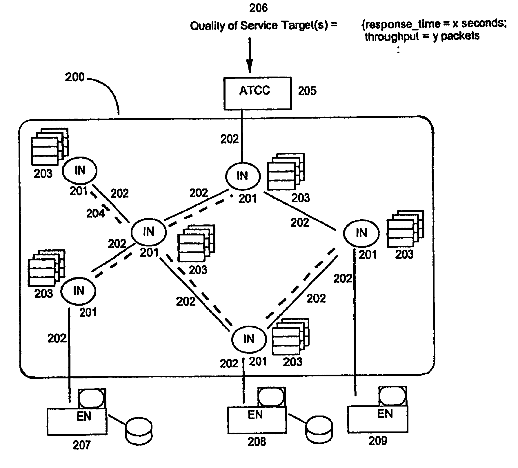
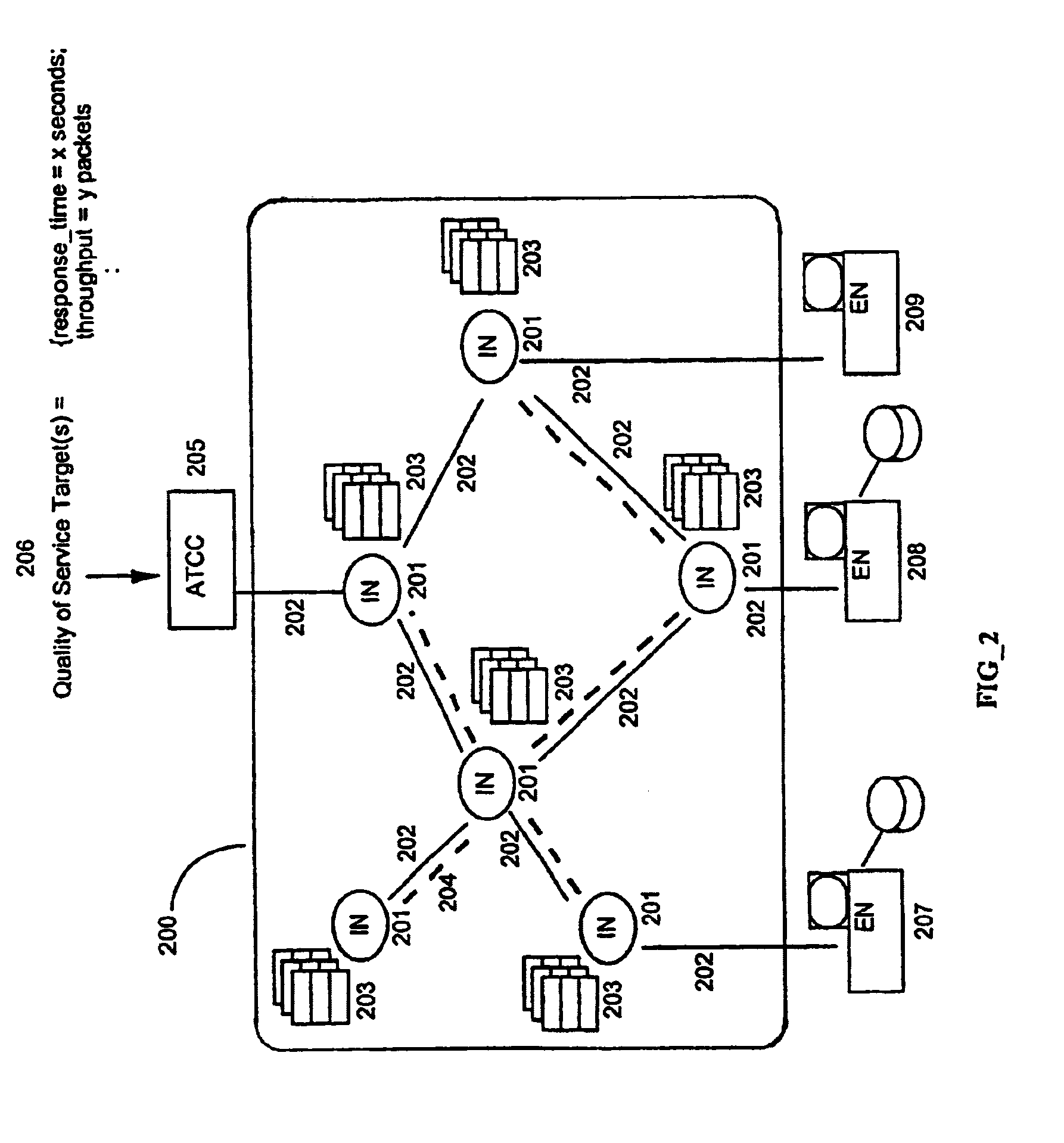
[0018]The foregoing and other objects of the invention are achieved by modeling the spatial traffic intensity distribution in a computer network and its spatial dynamics and temporal behavior. This is achieved by providing a population or traffic intensity map, similar to weather maps, for the discrete event system composed of the computer communications network and its traffic load. The plot of such a map over time describes the temporal and spatial dynamics of the discrete event system composed of the computer communications network and its traffic load. This provides information for controlling the quality of service variables. The control is achieved by a combination of (1) routing that minimizes transit through congested regions of the network, (2) by determining where content caches should be located in a computer communications network and when traffic should be directed to which cache location, (3) by determining when the network's topology and / or bandwidth should be changed to improve performance, and (4) by identifying local bandwidth surpluses or deficits as well as their persistence to enable bandwidth trading and / or network redesign.

Problems solved by technology

A direct consequence of the use of a spanning tree to determine the forwarding or routing tables is that highly robust networks, with many redundant links, are necessarily highly inefficient; and that highly efficient networks, with few if any unused links, are necessarily fragile and subject to interruption of service by faults.
In fact, topology adaptive routing protocols that rely on implicit or explicit spanning trees of necessity create bottlenecks.
However, computer networks are increasingly carrying large amounts of time sensitive traffic such as voice or video, both of which require highly consistent and predictable service from the network.
The challenge of controlling performance variables such as response time, jitter, and throughput—generally referred to collectively as Quality of Service (QoS)—is that knowledge of topology alone is inadequate.
But the inclusion of such traffic state information in the routing caused major difficulties with instabilities due to rapidly changing state information generated by volatile queue dynamics.
The result was large oscillations in routing as attempts to route traffic away from regions of congestion toward less utilized links suffered from overshoot, resulting in traffic bouncing between regions of the network as each region alternatively went from idle to congested and back again.
Another of the disadvantages of the prior art traffic-enhanced routing protocol approach has been the very substantial amounts of the network's total bandwidth consumed by the routing protocol's state updates, the frequency of which is determined by the volatility of the state information they are carrying.
Because of these disadvantages, attempts to generate traffic-adaptive paths are today largely limited to manual efforts, where human operators or network engineers estimate traffic patterns and lay out routes that will avoid congested regions.
It is widely recognized that this approach is neither accurate nor scalable: large networks will require tens of thousands of paths active at any given time, and generating these is simply beyond the capabilities of current or future network staffing.

Method used


Image

  • Automatic traffic and quality of service control system for communications networks
  • Automatic traffic and quality of service control system for communications networks
  • Automatic traffic and quality of service control system for communications networks

Examples


Embodiment Construction

[0025]A general description of the traffic intensity surface and maps and how they are constructed with the present invention can be illustrated by examining how weather maps are constructed. A weather map is a graphical depiction of the state of the atmosphere over a certain geographical region at a given time. To produce weather maps and weather predictions requires two systems: a monitoring system consisting of a number of instrumentation points where sensors are located to collect state information about the weather, including such variables as temperature, barometric pressure, etc.; and a meteorological modeling system that receives the state information thereby collected and which uses this information in conjunction with a mathematical model of the atmosphere's dynamics to predict the weather. The model, generally speaking, is implemented in the form of a software program that is stored on digital computer, although analogue computers can also be used in some circumstances to...


PUM


Abstract

The present invention is directed to a system for controlling the quality of service and availability in a communications network. The system includes a processor which samples queue state information from selected intermediate nodes in the network and processes the queue state information to produce a traffic intensity map. The processor includes memory for storing said traffic intensity throughout the network as a traffic intensity surface and is configured to use the traffic intensity surface to control traffic in the network.

Description

RELATED APPLICATIONS[0001]This application claims priority to Provisional Application Ser. No. 60 / 251,325 filed Dec. 5, 2000.BRIEF DESCRIPTION OF THE INVENTION[0002]This invention relates generally to the automatic monitoring and control of performance and quality of service variables including response time, throughput, and utilization as well as availability variables including reliability and maintainability in distributed parameter discrete event systems such as communication networks and more particularly to the modeling of traffic intensity and describing its temporal-spatial dynamics.BACKGROUND OF THE INVENTION[0003]A computer communications network is a composite discrete event system (DES) made up of two classes of servers: links, which effect the actual transportation of data between source and destination end nodes; and intermediate nodes, which relay data between links, thereby effecting the concatenation of links to provide end-to-end transport of data. Other terms of a...

Claims


Application Information

Patent Timeline
Patent Type & Authority Patents(United States)
IPC IPC(8): G06F15/173H04L12/56
CPCH04L45/02H04L45/028H04L45/302H04L45/124H04L45/14H04L45/12
Inventor BYRNES, PHILIPPE C.
Owner BYRNES PHILIPPE C
Learn More