
Antenna device and electronic timepiece

an antenna device and electronic timepiece technology, applied in the field of antenna devices and electronic timepieces, can solve the problems of complicated control and difficult mounting of antenna devices, and achieve the effect of reducing the occupying region of antenna devices

Active Publication Date: 2012-08-23
SEIKO EPSON CORP
View PDF6 Cites 14 Cited by
  • Summary
  • Abstract
  • Description
  • Claims
  • Application Information

AI Technical Summary

Benefits of technology

[0014]With this configuration, the first electrode constituting at least a part of the character plate in the antenna device is the electrical conductor portion which is formed of an electrical conductor material such that a function of receiving a positioning signal is exhibited when power is fed. Examples of the material for the electrical conductor portion include copper, aluminum, iron, gold, silver, or an alloy thereof. On the surface of the electrical conductor portion, the time display portion which displays the time indicated by the hour hand and the minute hand is formed. In this way, in the case of the character plate with the electrical conductor portion as a base material, the installation space is saved, and it is not necessary to take into consideration special design, such as rearrangement of other timepiece components, compared to the related art in which an antenna device is newly and separately provided in an electronic timepiece.Application Example 3
[0016]With this configuration, since the time display portion which is formed for visual recognition of the time of the electronic timepiece has the characteristics of an electrical, nonconductor, it is possible to avoid a situation in which circularly polarized waves which will reach the electrical conductor portion are attenuated by the time display portion. That is, the antenna device can maintain an excellent reception performance while functioning as a character plate.Application Example 4
[0020]According to this antenna device, the antenna device has the antenna unit and the reflective liquid crystal display unit corresponding to a character plate in an analog electronic timepiece. The antenna unit has a configuration in which the first electrode faces the second electrode through the dielectric layer. The reflective liquid crystal display unit has the liquid crystal panel portion and the light reflective portion which reflects light transmitted the liquid crystal panel portion and transmits light through the liquid crystal panel portion again. In this antenna device, since the first electrode of the antenna unit constitutes at least a part of the light reflective portion, unlike the related art, it is not necessary to take into consideration the arrangement of the electrode (conductive thin film) such that visual recognition of the time or the like is not obstructed, friction resistance, corrosion resistance, or the like. Therefore, it is possible to reduce the number of constituent elements of the antenna device while receiving electric waves, thereby achieving a reduction in the size of the electronic timepiece.Application Example 6
[0022]According to this antenna device, the antenna device has the antenna unit and the transmissive liquid crystal display unit corresponding to a character plate of an analog electronic timepiece. The antenna unit has a configuration in which the first electrode faces the second electrode through the dielectric layer. The transmissive liquid crystal display unit has the liquid crystal panel portion and the light source portion which emits light as a light source of the liquid crystal panel portion. In this antenna device, since the first electrode of the antenna unit constitutes at least one of the light source portion, unlike the related art, it is not necessary to take into consideration the arrangement of the electrode (conductive thin film) such that visual recognition of the time or the like is not obstructed, friction resistance, corrosion resistance, or the like. Therefore, it is possible to reduce the number of constituent elements of the antenna device while receiving electric waves, thereby achieving a reduction in the size of the electronic timepiece.Application Example 7
[0024]According to this electronic timepiece, the first electrode constitutes a character plate of an analog electronic timepiece, the light reflective portion of the reflective liquid crystal display unit which achieves a character plate function, or the light source electrode of the transmissive liquid crystal display unit which achieves a character plate function, making it possible to minimize the occupying region of the antenna device. Therefore, even when the antenna device is incorporated, the electronic timepiece can sufficiently achieve the function of receiving electric waves without being subjected to the restriction of design or the like.

Problems solved by technology

In the related art, these antenna devices are provided in electronic timepieces in which the antenna devices are difficult to be mounted due to the restriction of design, size, and the like.
However, according to the technique of JP-A-2003-66169, in order to increase communication sensitivity, there is the restriction that a material for a region of the display plate where the antenna is attached should be an insulating member, not a conductive member, and there is a problem from the viewpoint of selection of the material of the display plate, surface treatment relating to design, or the like.
According to the technique of JP-A-2007-124011, there are problems in that a plurality of elements should be arranged such that the reception characteristic directions cross each other, it is necessary to provide phase changing means for changing the phase of a received signal so as to show a phase difference based on the crossing angle of the reception characteristic directions, and complicated control should be performed.

Method used


Image

  • Antenna device and electronic timepiece
  • Antenna device and electronic timepiece
  • Antenna device and electronic timepiece

Examples


embodiment 1

[0038]First, as an example of a communication system which receives positioning signals from satellites and uses the positioning signals, a GPS system will be introduced, and the outline thereof will be described. As a communication system using satellites, in addition to a GPS system, there are WAAS (Wide Area Augmentation System), QZSS (Quasi Zenith Satellite System), GLONASS (GLObal NAvigation Satellite System), GALILEO, and the like. These systems may be used.

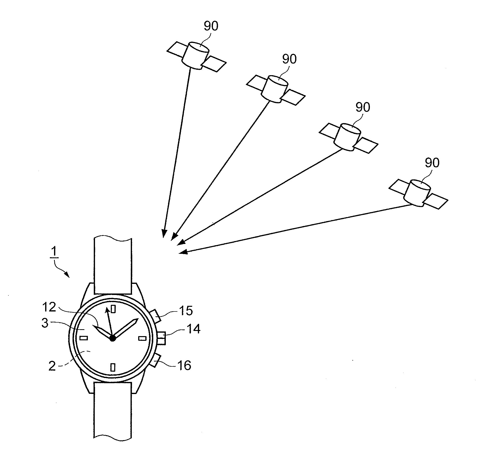
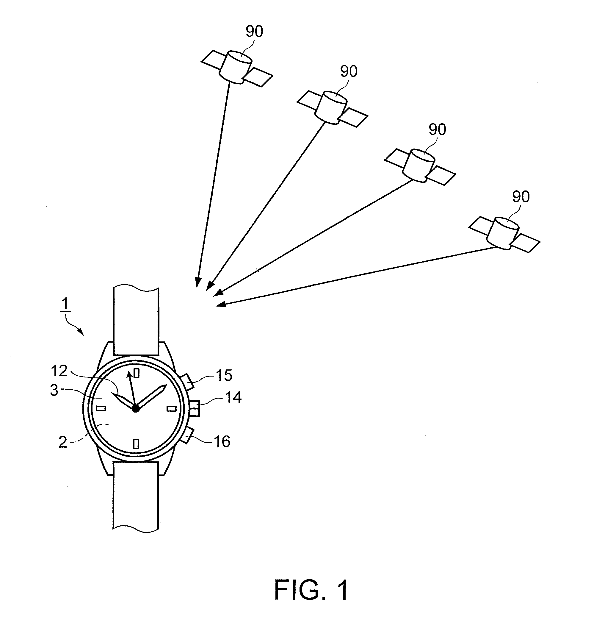
[0039]FIG. 1 is a schematic view showing the outline of a GPS system in Embodiment 1. As shown in FIG. 1, GPS satellites (satellites) 90 travel in a predetermined orbit above the earth, and transmit satellite signals, in which a navigation message or the like is superimposed on a microwave of 1.57542 GHz, to the ground. Each GPS satellite 90 has an atomic timepiece mounted therein, and the satellite signal includes GPS time information which is very accurate time information measured by the atomic timepiece. For this reason...

embodiment 2

[0064]Next, another embodiment of an antenna device will be described. In this case, an antenna device is mounted in a digital wristwatch (electronic timepiece), and a wristwatch includes a reflective liquid crystal display unit.

[0065]FIG. 6 is a schematic view showing the outline of a GPS system in Embodiment 2. As shown in FIG. 6, GPS satellites (satellites) 90 travel in a predetermined orbit above the earth, and transmit satellite signals to the ground. Each satellite signal includes GPS time information which is very accurate time information measured by an atomic timepiece. For this reason, a digital wristwatch (electronic timepiece) 100 having a function as a GPS receiver receives satellite signals to correct the advance or delay of the internal time, thereby displaying the accurate time. This correction is done as a time measurement mode.

[0066]The satellite signals also include orbit information which represents the position of the GPS satellite 90 in an orbit, or the like. T...

embodiment 3

[0082]Next, another embodiment of antenna device will be described. In this case, an antenna device is mounted in a digital wristwatch (electronic timepiece), and a wristwatch includes a transmissive liquid crystal display unit having a light source.

[0083]FIG. 11 is a sectional view showing an antenna device including an organic EL in Embodiment 3. As shown in FIG. 11, an antenna device 500 of a wristwatch 100A has an antenna unit 600, a transmissive liquid crystal display unit 700 which has an organic electroluminescence unit 710 (a light source, hereinafter, referred to as an organic EL unit) emitting white light, and a module 150 which has a driving mechanism for ticking or the like, or a processing mechanism for processing and displaying information.

[0084]The transmissive liquid crystal display unit 700 is configured such that a TFT (Thin Film Transistor) substrate 700a as a base, on which the transmissive liquid crystal display unit 700 is formed, and a counter substrate 700b w...


PUM


Abstract

An antenna device which is provided in an electronic timepiece, and receives positioning signals from satellites includes: a first electrode; a second electrode; and a dielectric layer arranged between the first electrode and the second electrode, wherein one electrode of the first electrode and the second electrode constitutes at least a part of a character plate of the electronic timepiece.

Description

[0001]This application claims priority to Japanese Patent Application No. 2011-036807, filed Feb. 23, 2011 and Japanese Patent Application No. 2011-181280, filed Aug. 23, 2011, the entirety of which are hereby incorporated by reference.BACKGROUND[0002]1. Technical Field[0003]The present invention relates to an antenna device capable of achieving reduction in size and an electronic timepiece including the antenna device.[0004]2. Related Art[0005]In the related art, for an antenna device which can be provided in an electronic timepiece, a configuration in which an antenna is provided to be bonded to a display plate (character plate) of an electronic timepiece is disclosed. With this configuration, the antenna is provided on the rear side of the display plate, that is, on a non-visible side, thereby avoiding the design appearance of the electronic timepiece from being damaged due to the antenna. The electronic timepiece can have a noncontact data communication function while substantia...

Claims


Application Information

Patent Timeline
Patent Type & Authority Applications(United States)
IPC IPC(8): G04C11/02G04G21/04G04R20/02G04R60/00G04R60/02G04R60/10
CPCG04R20/04G04R60/12H01Q9/0428H01Q9/0407H01Q1/273
Inventor AIZAWA, TADASHIFUJISAWA, TERUHIKO
Owner SEIKO EPSON CORP
Learn More