
Vehicle air duct assembly of an integrated beam structure

a beam structure and vehicle air technology, applied in vehicle maintenance, vehicle cleaning, transportation and packaging, etc., can solve the problems of increased logistics cost and production cost, increased production cost, and deterioration of rigidity and durability of products, so as to reduce the number of parts and increase the overall strength. , the effect of simplifying the manufacturing process

Inactive Publication Date: 2005-03-03
HYUNDAI MOBIS CO LTD +1
View PDF6 Cites 14 Cited by
  • Summary
  • Abstract
  • Description
  • Claims
  • Application Information

AI Technical Summary

Benefits of technology

The present invention is a vehicle air duct assembly that reduces the number of parts needed for assembly, simplifies the coupling structure of various parts, and minimizes noise from the coupling regions between parts. The assembly includes a front beam member integrated with an air vent duct and cowl cross bar, and brackets for attaching various electric equipment parts. A rear beam member is coupled to the rear side of the front beam member and guides parts of air flowing through the air vent duct towards the front of the automobile. The assembly is made from a combination of steel and thermoplastic resin, which increases overall strength and reduces weight.

Problems solved by technology

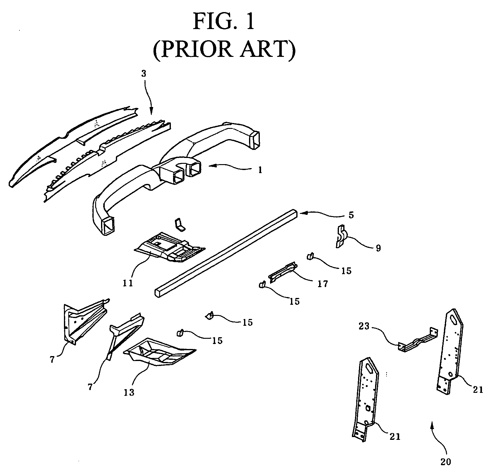
That is to say, the conventional air vent duct 1 is of a structure in which a plurality of parts is coupled to the cowl cross bar 5, thus the rigidity and durability of the product are deteriorated and there is a risk of noise generation when operating the vehicle due to the poor coupling between the parts.
Moreover, since each of the parts is manufactured individually, there is an increase in logistics cost and increase of production cost.
However, according to this type of air duct structure, since the parts are made only of a thermoplastic resin of a relatively small rigidity, the rigidity of the product is lower.
Further, in the case where there are optional parts which can be attached and detached, costs are increased in order to provide materials consistent with the specification of each product.

Method used


Image

  • Vehicle air duct assembly of an integrated beam structure
  • Vehicle air duct assembly of an integrated beam structure
  • Vehicle air duct assembly of an integrated beam structure

Examples


Embodiment Construction

[0031] Hereinafter, an airduct assembly according to a preferred embodiment of the present invention will be described in more detail referring to the drawings.

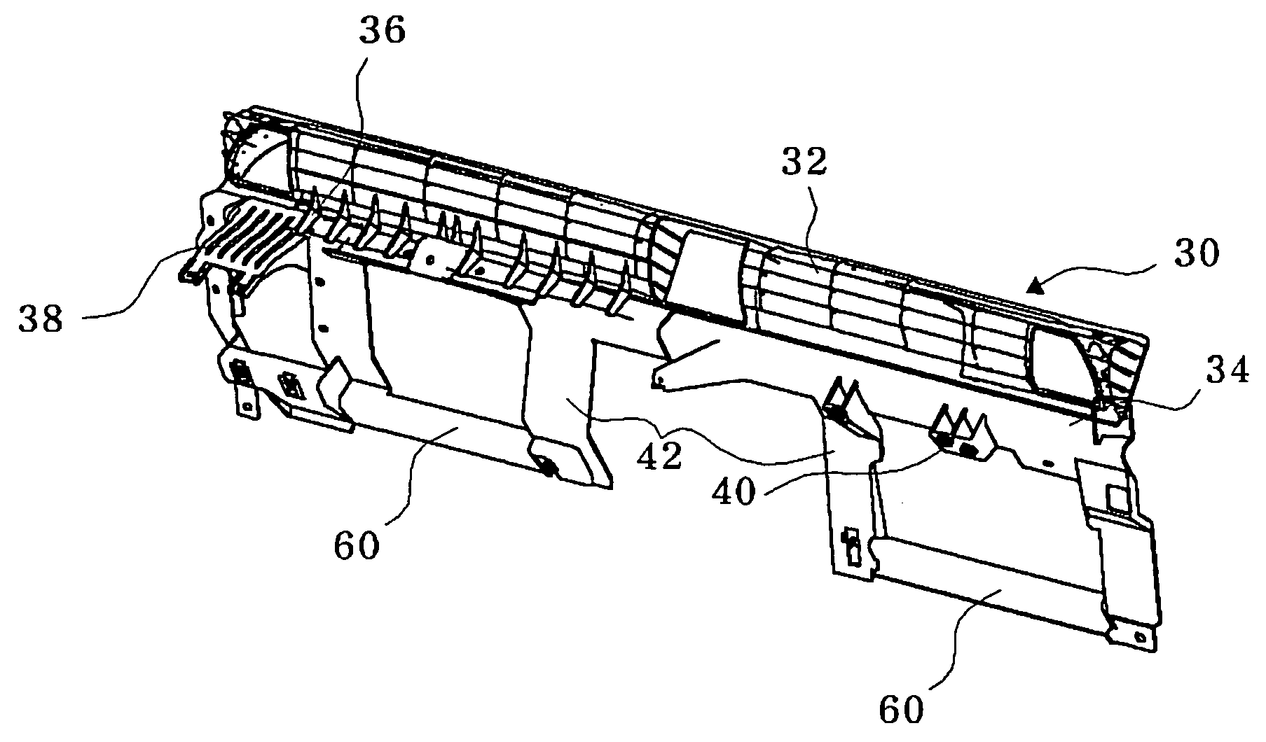
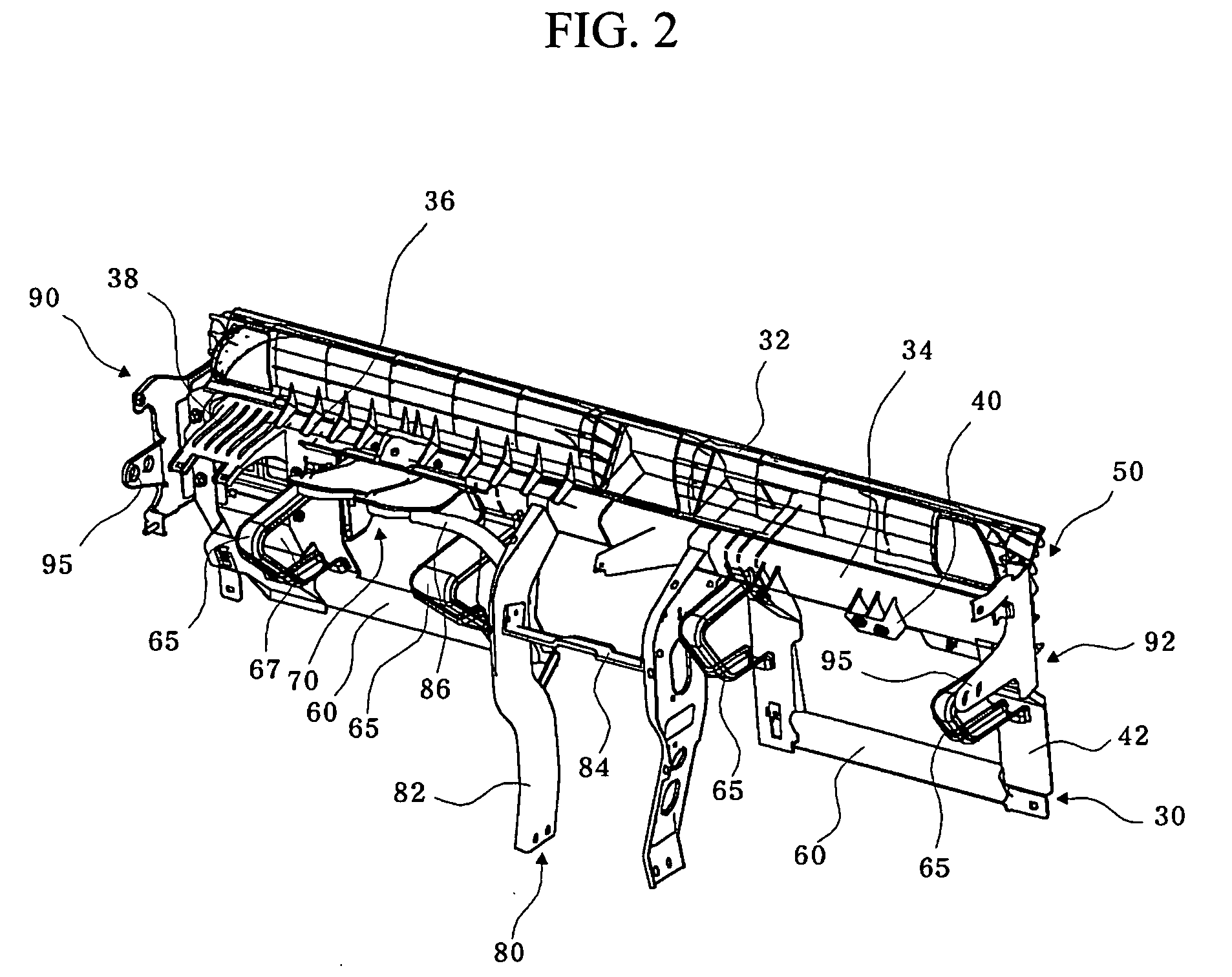
[0032]FIG. 2 is a perspective view showing a vehicle air duct assembly of an integrated beam structure according to an embodiment of the present invention. FIG. 3 is an exploded perspective view of FIG. 2. FIG. 4 is a perspective view showing a front beam member according to the embodiment of the present invention. FIG. 5 is a perspective view showing a center support according to the embodiment of the present invention. FIG. 6 is a perspective view showing a buffer member according to the present invention.

[0033] As shown in FIGS. 2 to 6, a vehicle air duct assembly of an integrated beam structure according to the embodiment of the present invention includes: a front beam member 30 having an air vent duct 32 and a cowl cross bar 34 formed integral with each other; and a rear beam member 50 of a duct coupled to the rear sid...


PUM


Abstract

A vehicle air duct assembly of an integrated beam structure includes a front beam member which is formed with an air vent duct for guiding air for the air conditioning of an automobile, a cowl cross bar for reinforcing the rigidity of the vehicle body and brackets for attaching a plurality of electrical equipment parts including an air bag; and a rear beam member which is coupled to the rear side of the front beam member and guides parts of air flowing through the air vent duct toward a front window glass of the automobile. According to the air duct, the number of parts is reduced, thus the manufacturing process is simplified, and a mixed material of steel and thermoplastic resin is used, thus the overall strength is increased and the weight is reduced.

Description

RELATED APPLICATION [0001] The present disclosure relates to subject matter contained in Korean application No.2003-55384, filed on Aug. 11, 2003, which is herein expressly incorporated by reference its entirety. BACKGROUND OF THE INVENTION [0002] 1. Field of the Invention [0003] The present invention relates to a vehicle air duct assembly of an integrated beam structure, and more particularly, to a vehicle air duct assembly of an integrated beam structure which can reduce the number of parts, the weight, and make attaching or detaching easier according to whether there is a need for parts for alleviating the impact from an accident, reducing the cost by forming the air duct and a cowl cross bar of a thermoplastic resin and forming the parts coupled to a steel material. [0004] 2. Description of the Related Art [0005] Generally, an apparatus for mounting electric parts of an automobile and an apparatus for guiding air for the ventilation, cooling, and heating of an automobile, are pr...

Claims


Application Information

Patent Timeline
Patent Type & Authority Applications(United States)
IPC IPC(8): B60H1/34B60H1/00B62D25/14
CPCB60H1/0055B62D25/145B62D25/142B60H1/34
Inventor LEE, JONG-WON
Owner HYUNDAI MOBIS CO LTD
Learn More