
Control apparatus for rotating machine

a control apparatus and rotating machine technology, applied in the direction of dynamo-electric converter control, motor/generator/converter stopper, dynamo-electric gear control, etc., can solve problems such as conventional techniques, and achieve the effect of suppressing the rapid change of current amplitud

Inactive Publication Date: 2006-05-09
MITSUBISHI ELECTRIC CORP
View PDF16 Cites 4 Cited by
  • Summary
  • Abstract
  • Description
  • Claims
  • Application Information

AI Technical Summary

Benefits of technology

[0017]According to the present invention, even if the rotation speed is rapidly changed by an impact load or the like, the primary angular frequency is changed according to the change in the rotation speed. Therefore, the rapid change in the current amplitude can be suppressed, and the problem that the overcurrent may possibly occur can be solved.

Problems solved by technology

However, the conventional techniques have the following problems.
As a result, there are a problem that a current transient response when a load torque increases differs from that when the load decreases even if the load torques in both cases are at an equal operating point, and a problem that a current transient response at a light load point differs from that at a heavy load point.
As a result, a current amplitude is rapidly changed, which may possibly cause overcurrent.

Method used


Image

  • Control apparatus for rotating machine
  • Control apparatus for rotating machine
  • Control apparatus for rotating machine

Examples


Embodiment Construction

[0025]Exemplary embodiments of a control apparatus for a rotating machine according to the present invention will be explained in detail with reference to the accompanying drawings.

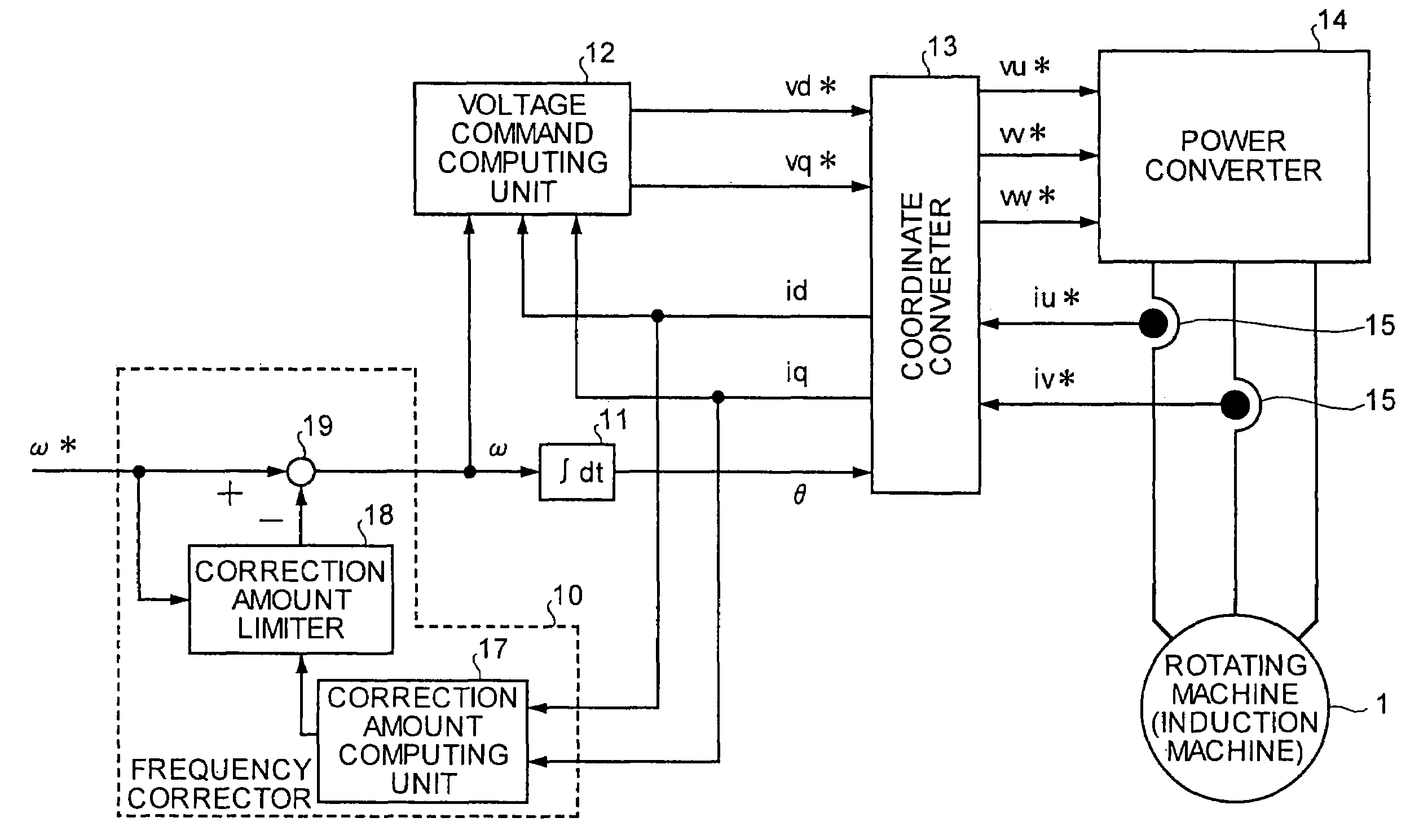
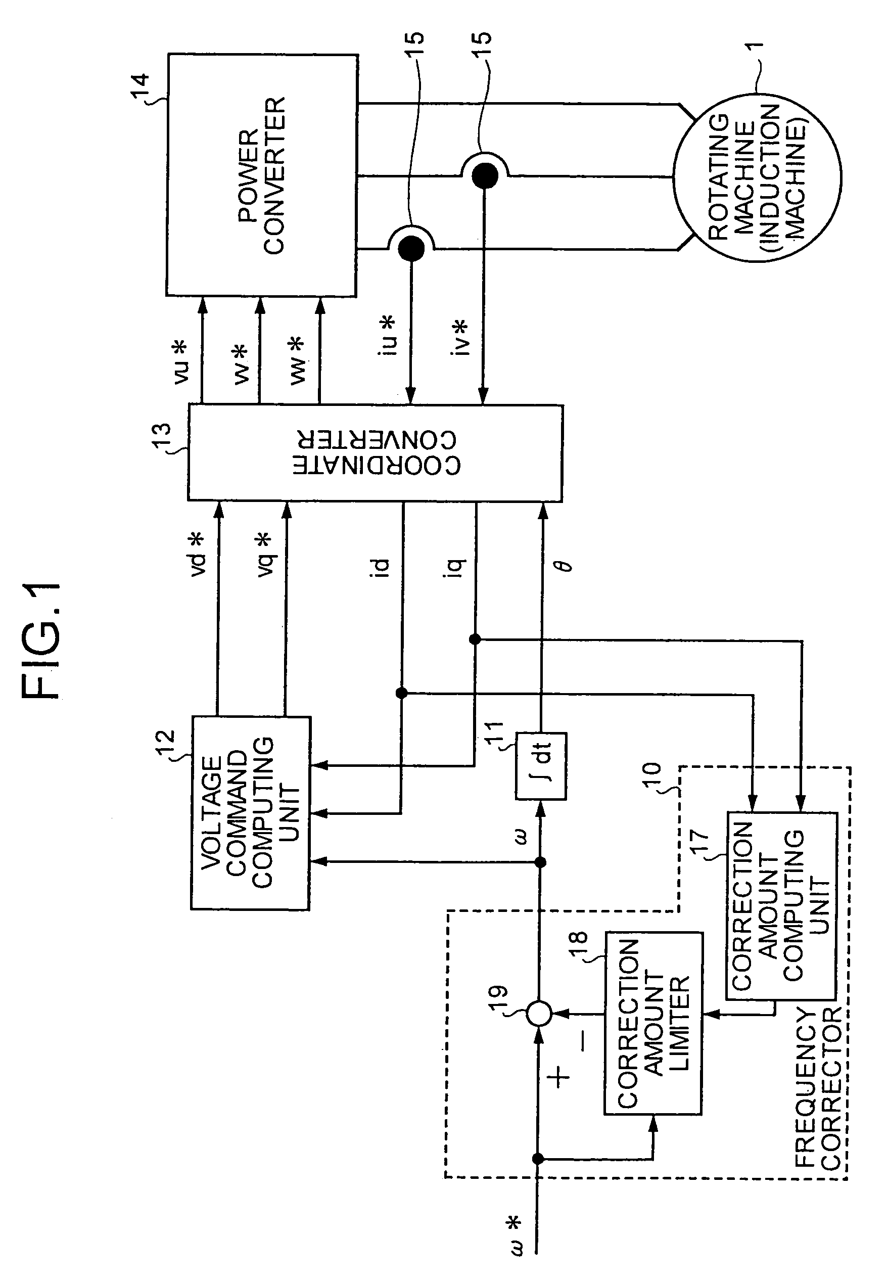
[0026]FIG. 1 is a block diagram of a configuration of a control apparatus for a rotating machine according to one embodiment of the present invention. As shown in FIG. 1, a control apparatus of a rotating machine (e.g., an induction motor) 1 according to this embodiment includes a frequency corrector 10, an integrator 11, a voltage command computing unit 12, a coordinate converter 13, a power converter 14, and a current detector 15.

[0027]The power converter 14 applies three phase voltages to the rotating machine 1 based on three phase voltage commands vu*, vv*, and vw* input from the coordinate converter 13.

[0028]The current detector 15 detects two phase currents iu and iv among three phase currents carried to the rotating machine 1, and outputs the detected phase currents iu and iv to the coordinate conv...


PUM


Abstract

In a control apparatus for a rotating machine, an integration unit integrates a primary angular frequency based on an angular velocity command and computes phase, a power converting unit applies three-phase voltages to the rotating machine according to three-phase voltage commands, a current detecting unit detects three-phase currents flowing through to the rotating machine, a coordinate converting unit converts the currents detected by the current detecting unit into currents on rotating two-axis coordinates based on the phase output by the integration unit and converts voltage commands on the rotating two-axis coordinates into the three-phase voltage commands, and a voltage command computing unit computes the voltage commands based on the absolute value of deviations of the primary angular frequency and the current components along each of the rotating two-axis coordinates.

Description

TECHNICAL FIELD[0001]The present invention relates to a control apparatus for a rotating machine.BACKGROUND ART[0002]Examples of a rotating machine include an induction machine and a synchronous machine. As a control apparatus for the induction motor, a control apparatus disclosed in, for example, Patent Literature 1 is conventionally known. Namely, as particularly shown in pages 8 to 12, FIGS. 1, 8, 9, 12, and 14, the Patent Literature 1 discloses the control apparatus for the induction motor, including a power conversion circuit that outputs an alternating-current primary voltage of a variable voltage at a variable frequency to drive the induction motor, a current detector that detects a primary current supplied from the power conversion circuit to the induction motor, a current component computing circuit that computes first and second current components from the primary current and a preset frequency command for the alternating-current primary voltage, a magnetic flux command co...

Claims


Application Information

Patent Timeline
Patent Type & Authority Patents(United States)
IPC IPC(8): H02P23/00H02P25/00H02P27/00H02P27/04H02P9/14H02P21/00H02P21/22H02P23/07H02P27/06
CPCH02P21/00H02P23/0036H02P21/0039H02P23/0004H02P21/24
Inventor KINPARA, YOSHIHIKOFURUTANI, SHINICHIKAITANI, TOSHIYUKI
Owner MITSUBISHI ELECTRIC CORP
Learn More