Image forming apparatus
a technology of image forming apparatus and forming apparatus, which is applied in the direction of electrographic process apparatus, instruments, optics, etc., can solve the problems of not being able to use the image forming apparatus right after a toner, the charging characteristics of toner to change a lot, and the inability to use the image forming apparatus. to achieve the effect of suppressing the rapid change of a density level
- Summary
- Abstract
- Description
- Claims
- Application Information
AI Technical Summary
Benefits of technology
Problems solved by technology
Method used
Image
Examples
first embodiment
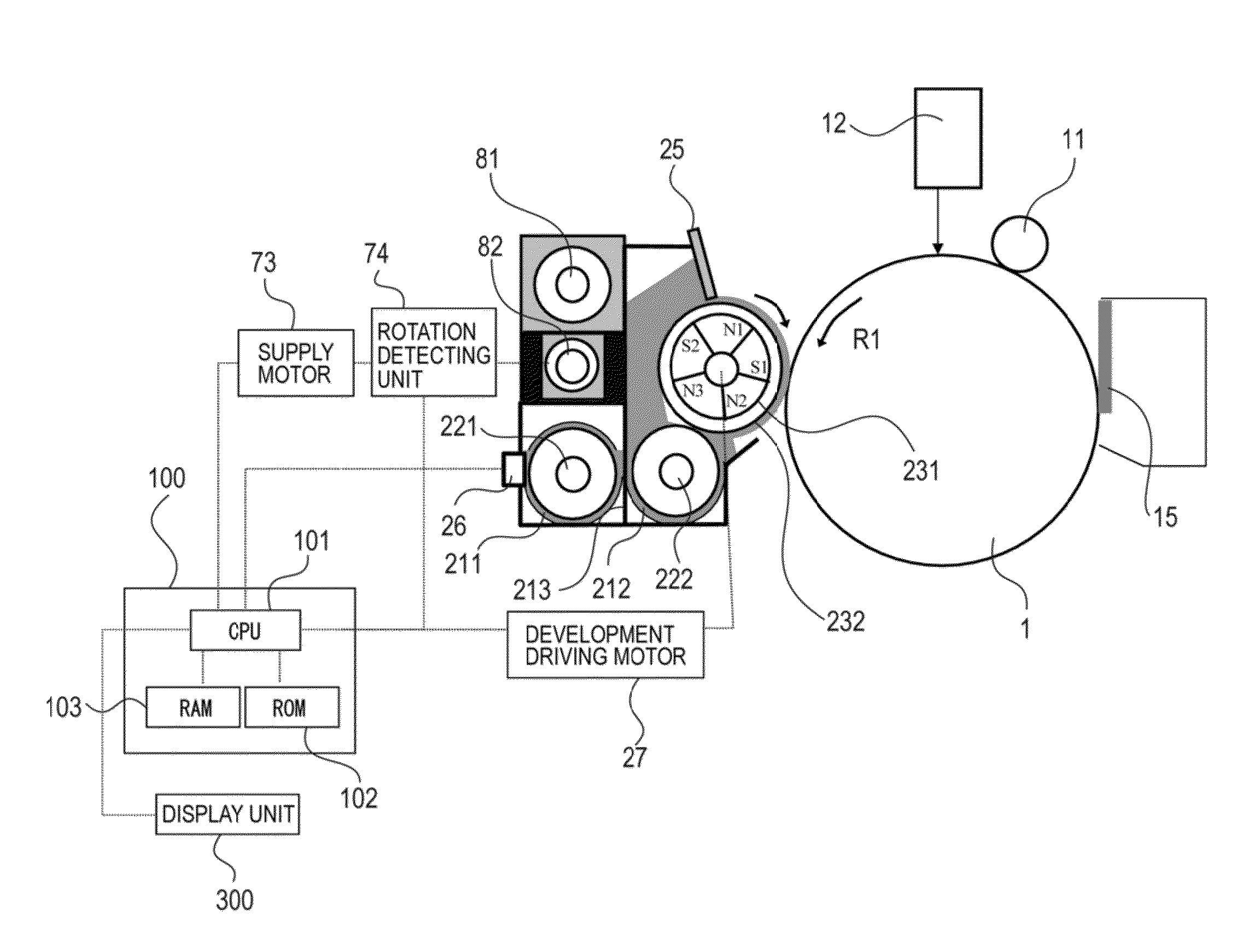
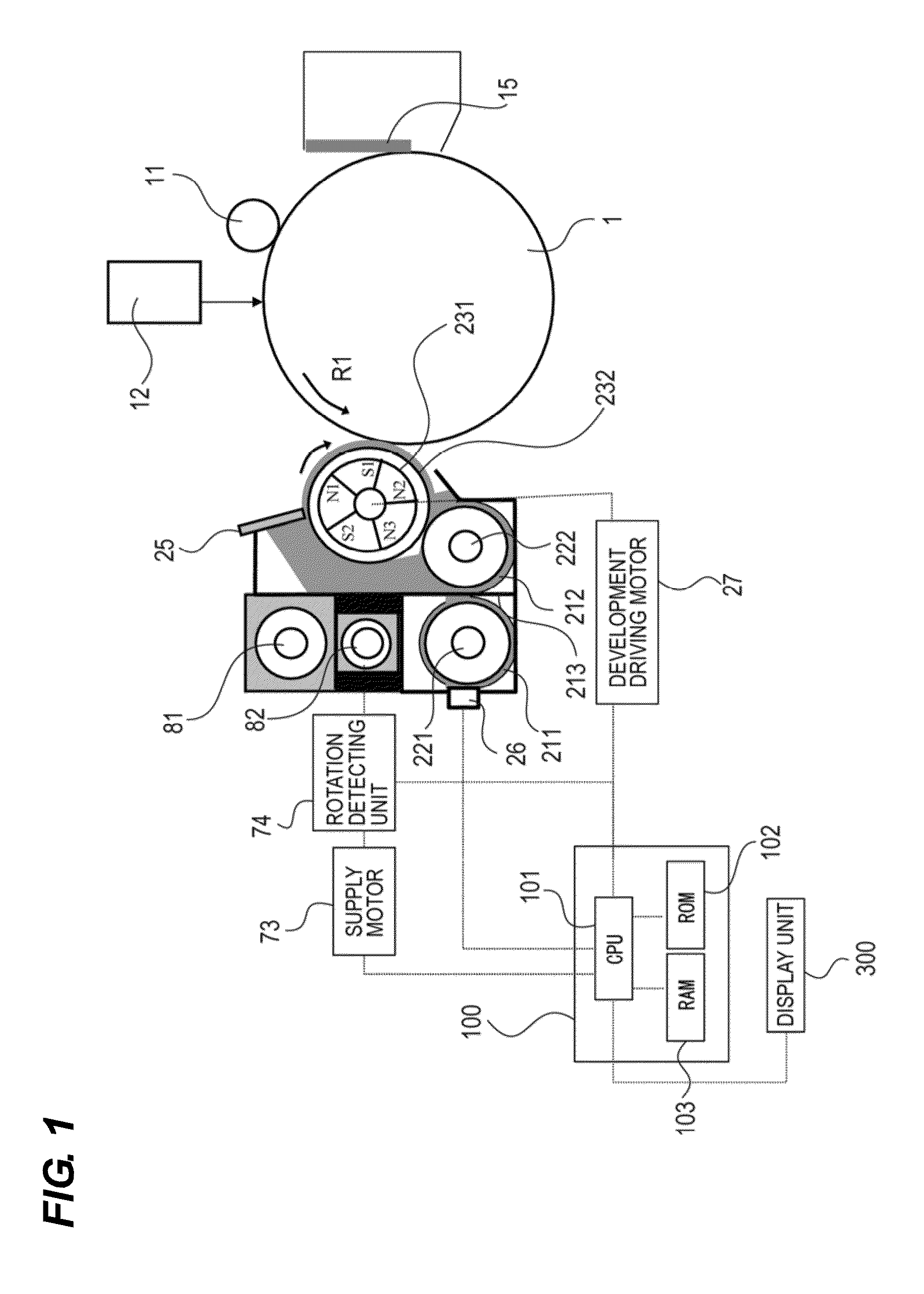
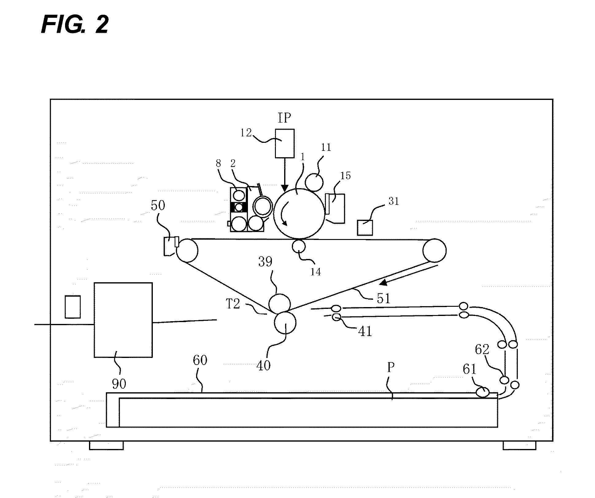
[0028]The first embodiment of the image forming apparatus of the present invention will be described hereunder with reference to the drawings. FIG. 2 is a schematic diagram showing the configuration of the image forming apparatus according to this embodiment.
[0029]As shown in FIG. 2, the image forming apparatus of this embodiment includes four image processing units IP according to yellow, magenta, cyan and black, respectively. The four image forming apparatuses are of the same structure. Therefore, in FIG. 2, the other three image processing units IP are omitted.
[0030]In each image processing unit IP, a laser beam according to image information is irradiated from the scanner 12 on the photosensitive drum 1 (image bearing member) which is charged by charging roller 11. The electrostatic latent image is developed as a toner image of each color with using toner of each color. The developed toner image of each color is primarily transferred on the intermediate transfer belt 51 so as to...
second embodiment
[0068]Next, the second embodiment of an image forming apparatus according to the present invention will be explained with reference to the drawings. The same reference numerals are used for the portions in which the same explanation is made as the first embodiment and redundant explanations are omitted.
[0069]In the first embodiment, as the coefficient for use in calculating the inductance supply amount M_Indc in the toner bottle initial period, one kind of coefficient is used. In this embodiment, two kinds of coefficients are provided, which are used to calculate the inductance supply amount M_Indc in the toner bottle initial period and one of the two kinds of the coefficient is selected according to the magnitude relation of TD_target and TD_Indc(N−1).
[0070]If TD_target≧TD_Indc of (N−1), that is if the TD ratio is smaller than the target value, A_Indc and A_Indc_init are used. On the other hand, if TD_target<TD_Indc of (N−1), that is, if TD ratio is larger than the target value, IC...
third embodiment
[0074]Next, the third embodiment of an image forming apparatus according to the present invention will be explained. The same reference numerals are used for the portions in which the same explanation is made as the first embodiment or the second embodiment and redundant explanations are omitted.
[0075]Instead of or in addition to changing the coefficients of the first and second embodiments, this embodiment has the following configuration. That is, an upper limit (maximum value) of inductance supply amount M_Indc of the first and second embodiments is set. Thereby, even if the difference value between TD_target and TD_Indc(N−1) is large, inductor supply amount M_Indc does not become too large. Therefore, according to the present embodiment, transition of the TD ratio after replacement of the toner bottle becomes gentle and the level of density fluctuation can be suppressed like the first and second embodiments.
[0076]In the toner bottle initial period of the present embodiment, the u...
PUM
 Abstract
Description
Claims
Application Information
 - R&D
- Intellectual Property
- Life Sciences
- Materials
- Tech Scout
- Unparalleled Data Quality
- Higher Quality Content
- 60% Fewer Hallucinations
Browse by: Latest US Patents, China's latest patents, Technical Efficacy Thesaurus, Application Domain, Technology Topic, Popular Technical Reports.
© 2025 PatSnap. All rights reserved.Legal|Privacy policy|Modern Slavery Act Transparency Statement|Sitemap|About US| Contact US: help@patsnap.com


