Ion beam device and method for cleaning gas field ion source
A technology of ion beam and gas field, which is applied in the manufacture of ion beam tubes, electrical components, discharge tubes/lamps, etc., can solve the problems of small size of ion generation source and narrow energy band width of gas ions, so as to reduce concentration and suppress The effect of rapid changes
- Summary
- Abstract
- Description
- Claims
- Application Information
AI Technical Summary
Problems solved by technology
Method used
Image
Examples
Embodiment 1
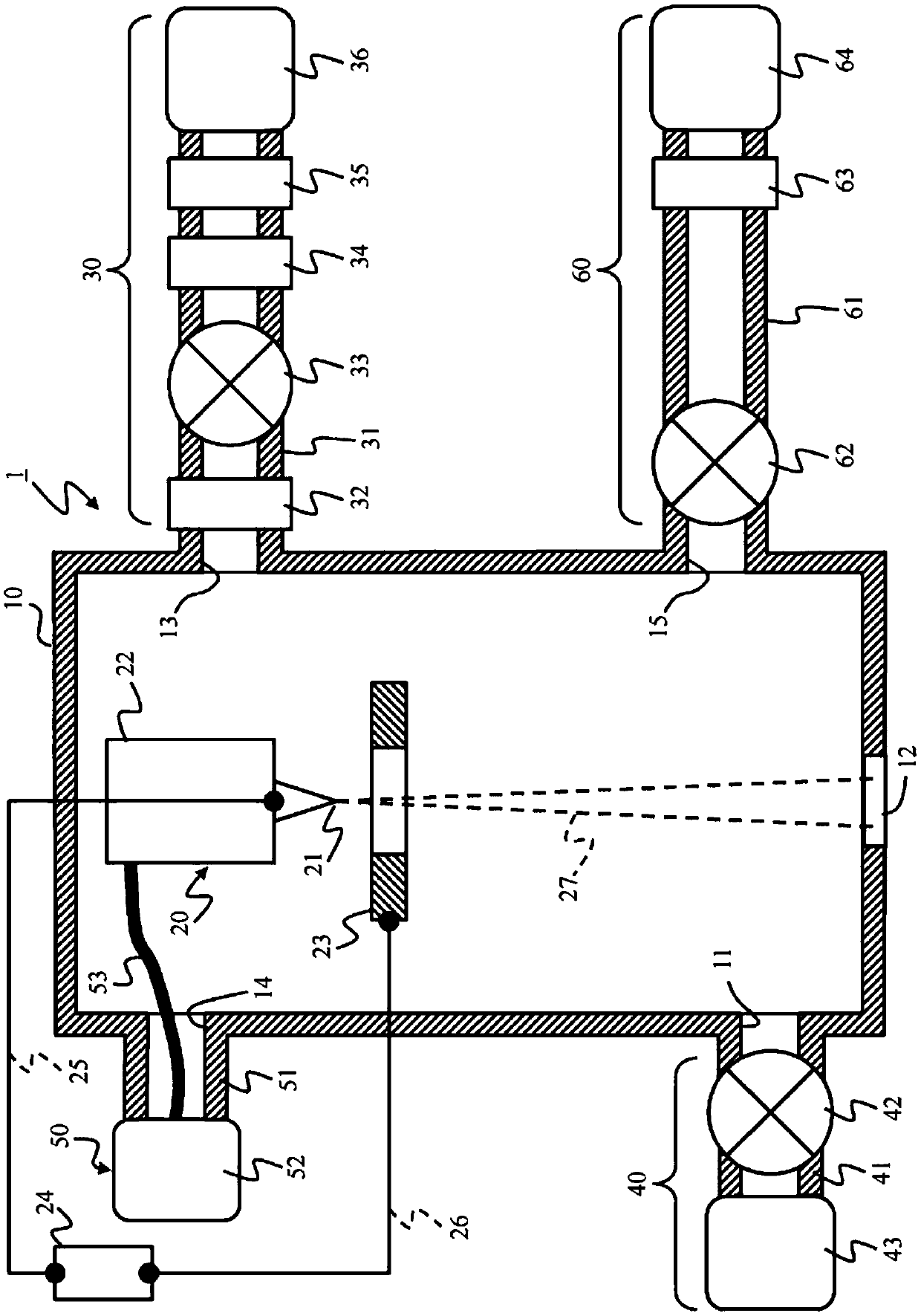
[0033] use Figure 1 to Figure 5 , the first embodiment will be described. figure 1 It is an overall configuration diagram of the gas field emission ion source 1 . Hereinafter, the gas field emission ion source 1 may be referred to as GFIS1.
[0034]
[0035] GFIS1 is equipped with the chamber 10, the ion generator 20, the gas supply system 30 for ionization, the exhaust system 40, the cooling system 50, and the gas supply system 60 for cleaning, for example.
[0036] Inside the chamber 10 serving as a vacuum container, an emitter electrode 21 of an ion generating device 20 is provided. An exhaust port 11 , a differential exhaust port 12 , an ionization gas supply port 13 , a cooling system connection port 14 , and a cleaning gas supply port 15 are formed in the chamber 10 .
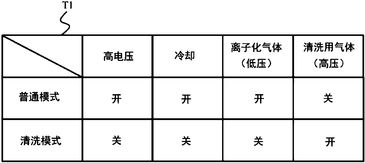
[0037] The gas in the chamber 10 is exhausted from the exhaust port 11 . The ion beam 27 is supplied to an unillustrated ion optical system 120 (see Figure 7 ). An ionization gas supply system 3...
Embodiment 2
[0099] The second embodiment will be described below. Since each of the following examples including this example corresponds to a modified example of the first example, the description will focus on differences from the first example. The basic structure and operation of GFIS1 are the same as those of the first embodiment. The difference from the first embodiment lies in the details of the purge gas.
[0100] The cleaning gas and ionizing gas in this embodiment are helium gas as in the first embodiment. However, in the first embodiment, the cleaning gas and the ionizing gas are helium gas with the same purity, but in the present embodiment, the cleaning gas has a lower purity than the ionizing gas. That is to say, the helium purity of the gas storage bottle 64 in this embodiment is lower than the helium purity of the gas storage bottle 36 .
[0101] Usually the helium sold in the market is of sufficiently high purity, and the amount of impurity gas contained therein is sig...
Embodiment 3
[0104] The third embodiment will be described below. The basic structure and operation of GFIS 1 of the third embodiment are also the same as those of the first embodiment. The difference between this embodiment and the first embodiment lies in the details of the purge gas. In this embodiment, hydrogen (H2) is used as the cleaning gas.
[0105] In the first embodiment and the second embodiment, the same helium gas as the ionization gas is used as the cleaning gas, but a gas with a molecular weight smaller than the ionization gas is used as the cleaning gas. The gas reduction effect will be better. Among them, when hydrogen gas is used as the cleaning gas, the effect of reducing impurity gas is large. As long as the cleaning gas is either an inert gas or a hydrogen gas, a new chemically active impurity gas that affects the tip of the emitter electrode 21 is not generated.
[0106] The present embodiment configured in this way also has the same effects as those of the first ...
PUM
 Abstract
Description
Claims
Application Information
 - R&D
- Intellectual Property
- Life Sciences
- Materials
- Tech Scout
- Unparalleled Data Quality
- Higher Quality Content
- 60% Fewer Hallucinations
Browse by: Latest US Patents, China's latest patents, Technical Efficacy Thesaurus, Application Domain, Technology Topic, Popular Technical Reports.
© 2025 PatSnap. All rights reserved.Legal|Privacy policy|Modern Slavery Act Transparency Statement|Sitemap|About US| Contact US: help@patsnap.com


