
Control device for vehicle and control method for vehicle

a control device and vehicle technology, applied in mechanical equipment, transportation and packaging, gear shifting, etc., can solve the problems of rapid decrease of the input shaft rotation speed of the automatic transmission, and the decrement of the driving comfort, so as to suppress the rapid change of the input shaft rotation speed

Active Publication Date: 2018-01-25
TOYOTA JIDOSHA KK
View PDF0 Cites 2 Cited by
  • Summary
  • Abstract
  • Description
  • Claims
  • Application Information

AI Technical Summary

Benefits of technology

The patent text describes a method to prevent rapid changes in the speed of an automatic transmission during gear shifts. This is particularly important when a jump gear shift is performed using an intermediate shift stage. The method involves performing a torque phase control to quickly disengage the frictional engagement elements and prevent the clutch torque from remaining, thus reducing the input shaft rotation speed. This allows for a smoother gear shift and prevents damage to the transmission.

Problems solved by technology

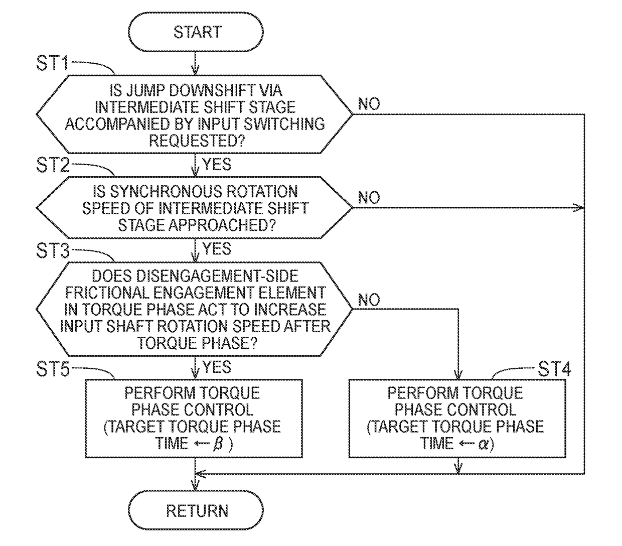
When a gear shift via an intermediate shift stage is performed accompanied by input switching in this way, there is a likelihood that a hydraulic response delay of a disengagement-side frictional engagement element or the like at the time of passing through the intermediate shift stage will occur and an input shaft rotation speed will change rapidly in the middle of the gear shift in a state in which a clutch torque after a torque phase remains.
In this case, degradation in drivability is caused.
Similarly, when a jump upshift via an intermediate shift stage is performed and a disengagement delay of a disengagement-side frictional engagement element occurs during a gear shift to the intermediate shift stage, there is concern that the input shaft rotation speed of the automatic transmission will decrease rapidly.
Accordingly, the above-mentioned hydraulic response delay or the like is likely to occur and there is a likelihood that the clutch torque of the frictional engagement element which is disengaged at the time of passing through the intermediate shift stage will remain.

Method used


Image

  • Control device for vehicle and control method for vehicle
  • Control device for vehicle and control method for vehicle
  • Control device for vehicle and control method for vehicle

Examples


Embodiment Construction

[0032]Hereinafter, an embodiment of the disclosure will be described with reference to the accompanying drawings.

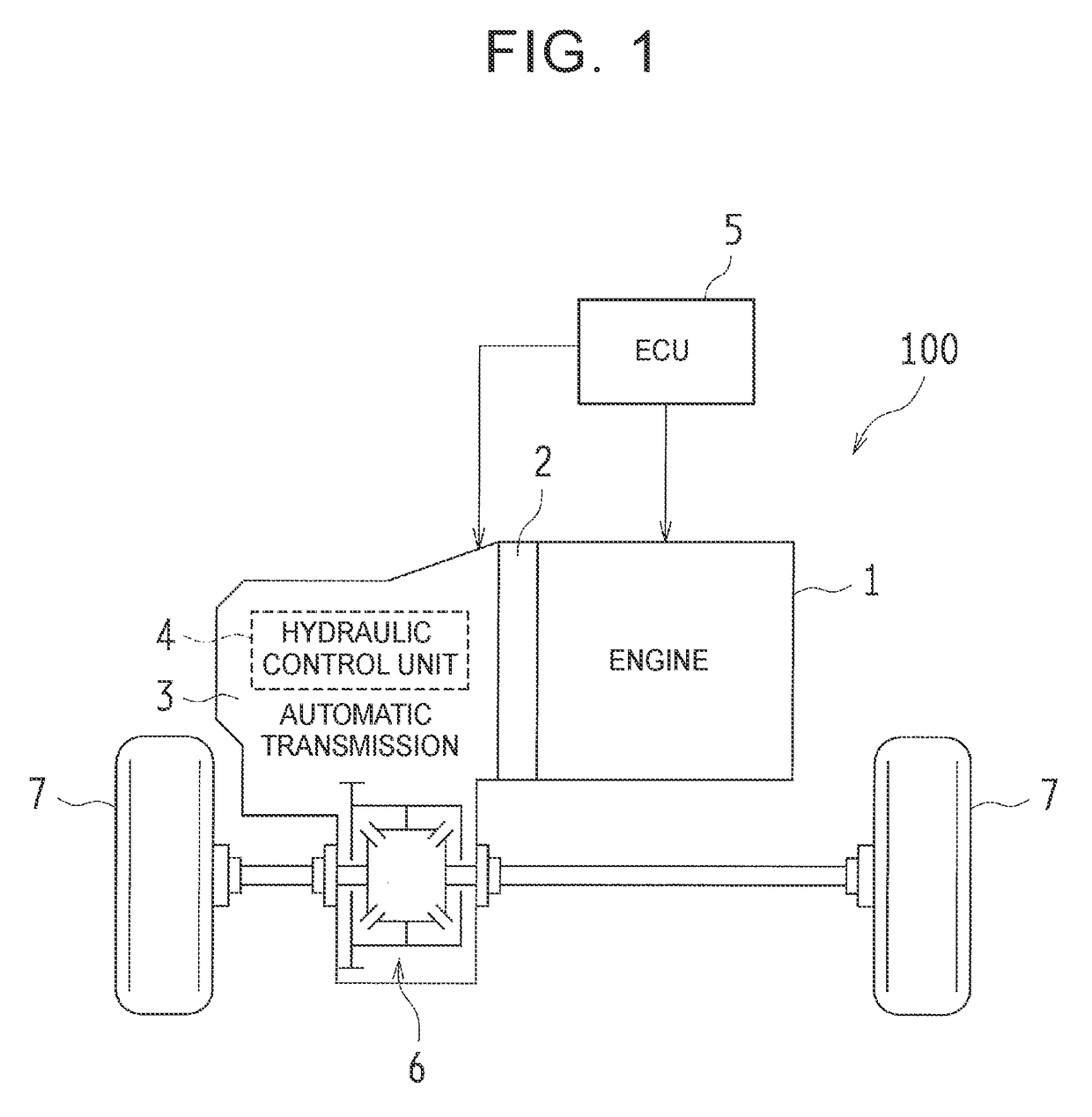
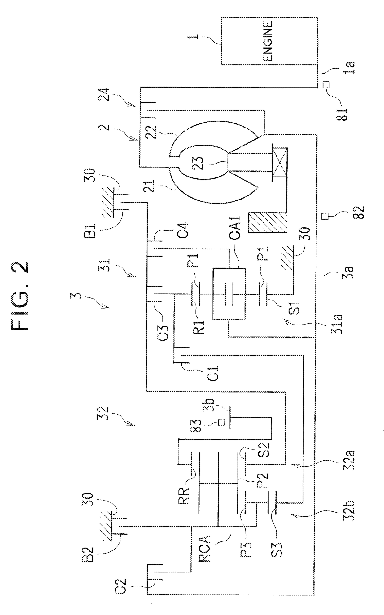
[0033]First, a vehicle 100 according to the embodiment will be described below with reference to FIGS. 1 to 4.

[0034]As illustrated in FIG. 1, the vehicle 100 includes an engine 1, a torque converter 2, a stepped type automatic transmission 3, a hydraulic control unit 4, and an electronic control unit (ECU) 5. The vehicle 100 is, for example, of a front engine-front drive (FF) type and is configured such that an output of the engine 1 is transmitted to a differential device 6 via the torque converter 2 and the automatic transmission 3 and is assigned to right and left driving wheels (front wheels) 7.

[0035]The engine (internal combustion engine) 1 is a driving force source for traveling and is, for example, a multi-cylinder gasoline engine. The engine 1 is configured such that an operation state thereof can be controlled based on a throttle opening level (an amount of intak...


PUM


Abstract

When a power-on downshift via an intermediate shift stage accompanied by input switching control is required and a predetermined shift stage is a shift stage lower than the intermediate shift stage, an electronic control unit performs torque phase control in a torque phase control time shorter than the torque phase control time that is set when the predetermined shift stage is a shift stage higher than the intermediate shift stage. Accordingly, it is possible to complete disengagement of a disengagement-side element early and to suppress a rapid increase of an input shaft rotation speed due to a clutch torque remaining.

Description

INCORPORATION BY REFERENCE[0001]The disclosure of Japanese Patent Application No. 2016-143527 filed on Jul. 21, 2016 including the specification, drawings and abstract is incorporated herein by reference in its entirety.BACKGROUND1. Technical Field[0002]The disclosure relates to a controller for a vehicle and a control method for a vehicle. Particularly, the disclosure relates to gear shift control when a gear shift via an intermediate shift stage is performed in a stepped type automatic transmission.2. Description of Related Art[0003]With a recent increase in the number of shift stages of an automatic transmission, a gear shift of an automatic transmission has more often been performed by a jump gear shift (for example, a gear shift from a current shift stage to a shift stage lower by two or more stages than the current shift stage at the time of a power-on downshift).[0004]When such a jump gear shift is performed, a variation in rotation speed of frictional engagement elements due...

Claims


Application Information

Patent Timeline
Patent Type & Authority Applications(United States)
IPC IPC(8): F16H61/04F16H61/686F16H61/682
CPCF16H61/0437F16H61/682F16H61/686F16H2061/0448F16H2306/14F16H2200/2097F16H2200/006F16H2200/0069F16H2200/201F16H2200/2046F16H3/666
Inventor OTA, KEISUKESAGAWA, AYUMUIWAMI, TOMOYA
Owner TOYOTA JIDOSHA KK
Learn More