
Electroionic processing system

Active Publication Date: 2006-04-25
BIOIONIX
View PDF10 Cites 39 Cited by
  • Summary
  • Abstract
  • Description
  • Claims
  • Application Information

AI Technical Summary

Benefits of technology

[0019]The present invention provides a particularly useful form of electroionics, which employs high frequency electromagnetic fields for electroionic processing. Such high frequency electromagnetic fields provide more efficient electroionic and chemical reactions that are more widely distributed in the aqueous solution.
[0026]The direct and capacitively-coupled electroionic processing embodiments preferably include at least two electrodes, but may include a plurality of electrodes. The direct and capacitively-coupled electroionic processes have a number of advantages in certain size installations. The electric power efficiency is good for small and medium-sized water and wastewater treatment plant installations. In small to medium water and wastewater treatment plant installations, the direct and capacitively-coupled electroionic processes have lower capital costs than the inductive electroionic process method. The direct and capacitively-coupled electroionic processes also are simpler in both concept and operation than the inductively-coupled electroionic process. The inductively-coupled electroionic process has a number of advantages in larger-sized water and wastewater treatment plant installations.
[0028]The present invention also includes process control by measuring microbial content, hydrogen peroxide and conductivity of the aqueous solution being treated by an on-line microbial analyzer, a H2O2 analyzer and a conductivity analyzer that are inputs to a process controller for adjusting the power level of the high frequency AC power supply that affect the electric field produced and the hydrogen peroxide generated based on the conductivity of the aqueous solution being treated. The higher the conductivity compared to the amount of power put in, the more effect you have because the current density generated is proportional to the strength of the field and the conductivity. Wastewater has a high conductivity. Biosolids have a higher conductivity. Potable waster has a lower conductivity. The present invention also allows for measurement of dissolved oxygen, COD, TOC and BOD (off-line) of the aqueous solution being treated. COD, TOC and BOD are measurements of organic material in the aqueous solution being treated.

Problems solved by technology

The treatment of wastewater does not provide water suitable for human consumption, either by drinking, use in cooking, washing of food products for consumption and the like.
These byproducts have been shown to cause cancer and birth defects in children.
Also, chlorination at non-toxic dosage levels, is not capable of inactivating Cryptosporidium, a major disease-causing parasite.
This is a costly process.
While UV disinfection systems offer the primary current alternative to chlorination, they also have serious limitations.
In large-scale disinfection systems, they do not effectively provide the required disinfection.
Also, in high turbidity water or wastewater, disinfection action is erratic and unpredictable due to absorption and scattering of the efficacious light.
Although ozone is a very effective disinfectant, it breaks down quickly and cannot be used to maintain disinfection in a distribution system.
Renovating water treatment plants so that they can use ozonation can be expensive.
Ozonation systems are cost effective only in very large-scale water and wastewater treatment plants.
Although such systems have been developed, the required high voltage power supply is very costly and also may raise serious safety problems.
Electroporation disinfection systems also consume large amounts of electric power.
Electroporation systems have disadvantages not only from the cost, but also from the practicality of the system as applied to large water utility and wastewater applications.
Further, requirements for large flow cells within closed systems or open channels limit the current state of the art in electroporation systems.
At the treatment plant level, voltage values and power consumption are significantly large and raise concerns for both safety and cost effectiveness.
Both of these DC techniques are characterized by efficient disinfection in small labaoratory-scale processes, inefficient disinfection in large-scale processes, and significant electrode contamination after prolonged operation.
Both technologies are not efficient or cost-effective in large-scale plant-size operations.
The '364 patent, however, does not establish that such metal removal could be accomplished in a cell of reasonable and cost effective size, particularly in high flow rates systems.
The prior art electromagnetic field approaches to wastewater disinfection and / or organics oxidation have failed to achieve the required efficiency levels in large-scale disinfection operations.
DC-based systems are also susceptible to electrode contamination.
Electroporation systems have found use only in limited, point-of-use applications where small pipe diameters are the rule.
However, commercially applicable systems for water treatment plants and large-scale wastewater processing have not found significant application.
These systems, however, use metals such as zinc, copper, lead, silver or the like which introduce toxic ions into the water.
It is submitted that such suggested systems cannot operate at the flow rate in channel or pipe sizes required for municipal water / wastewater treatment plants or other high volume applications.
Further, the prior ionic disinfection art has universally relied on metal electrodes which introduce undesirable and significant toxic metals into the treated water system, and particularly systems which would not function practically in the channel or pipe sizes at the high rates of flow encountered in modern day community water and wastewater treatment systems.

Method used


Image

  • Electroionic processing system
  • Electroionic processing system
  • Electroionic processing system

Examples


Embodiment Construction

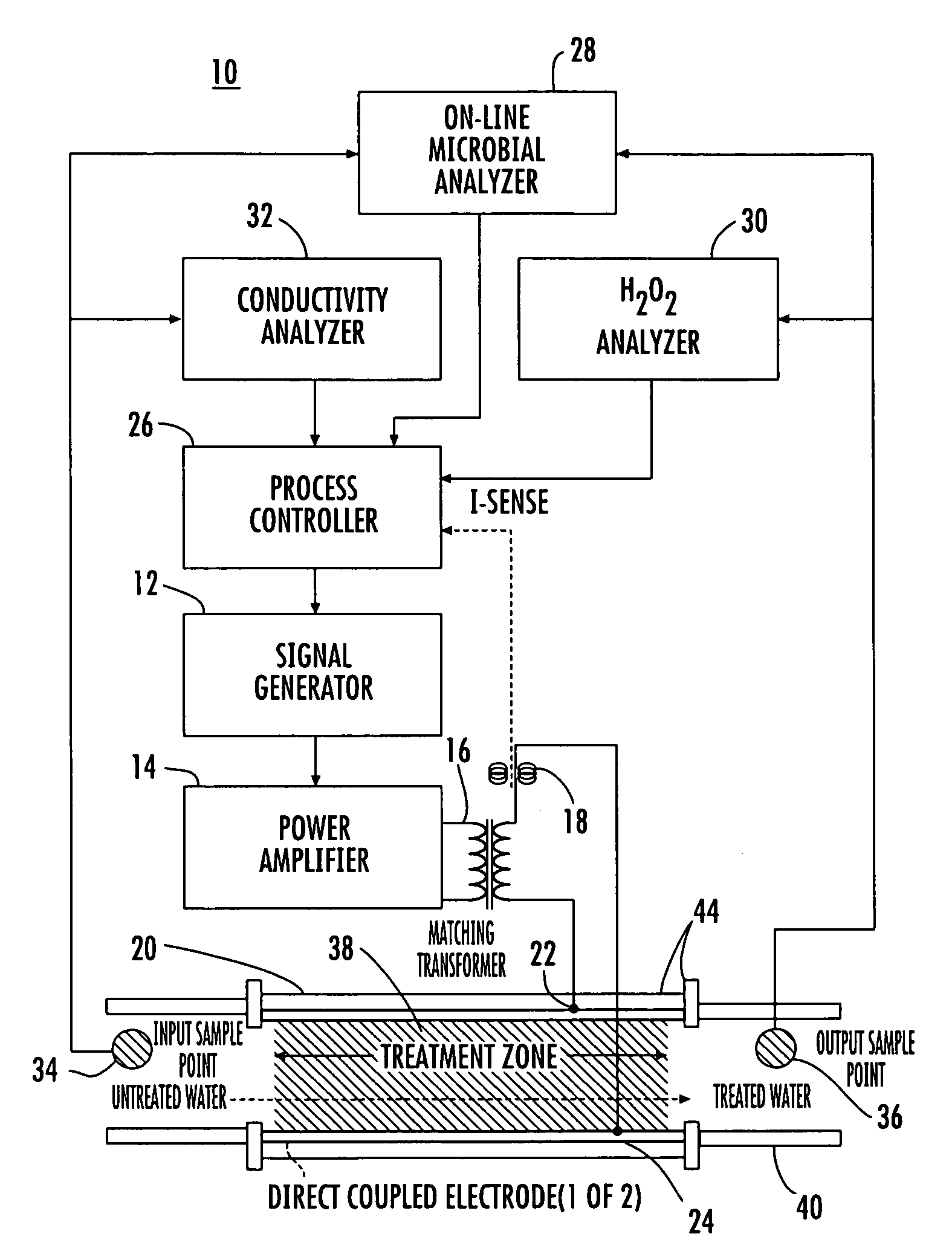
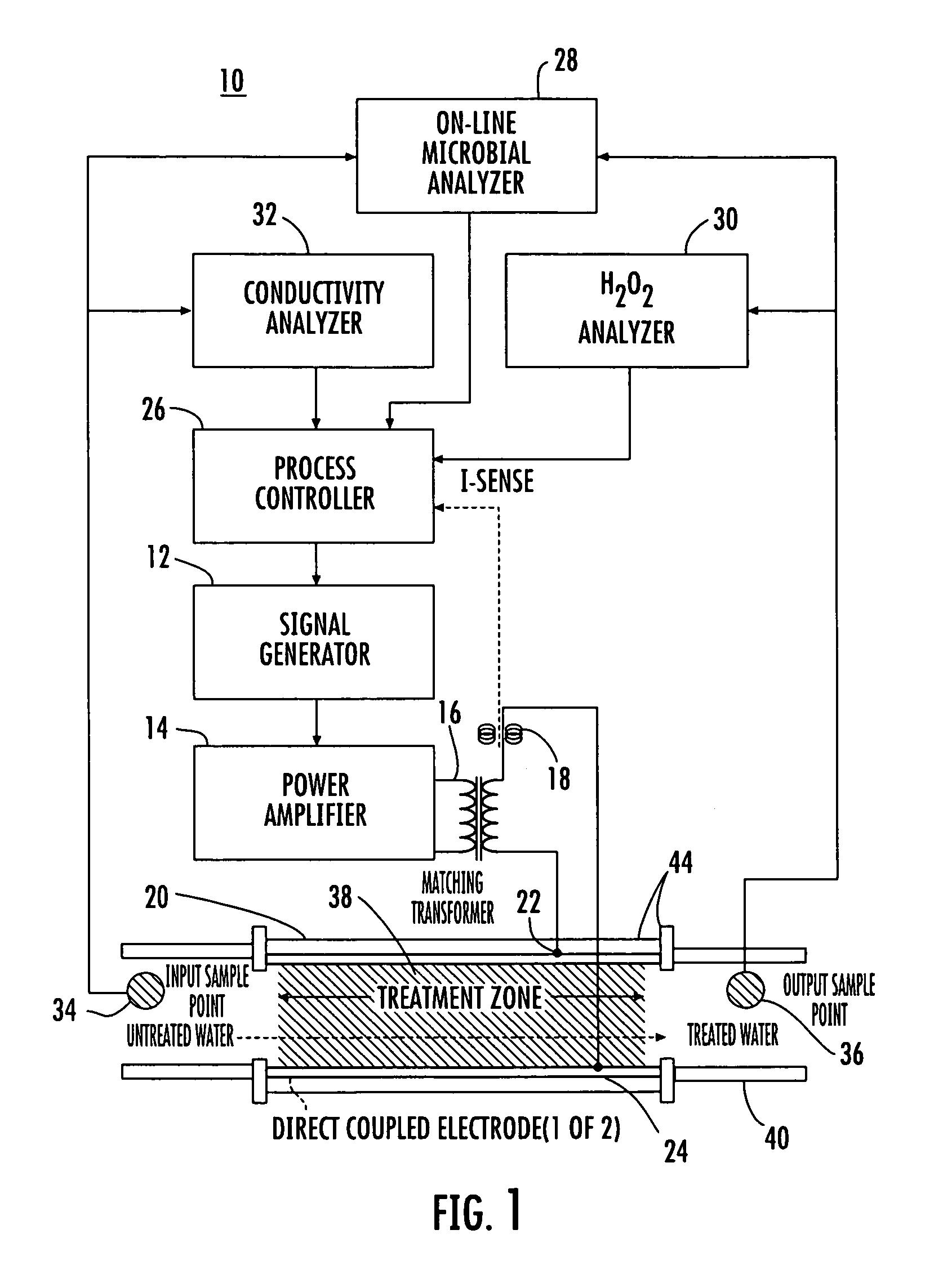
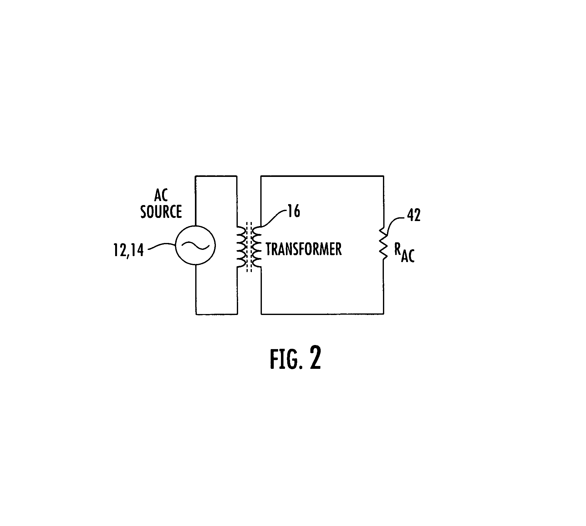
[0043]Referring to the drawings and particularly to FIG. 1, a block diagram of a direct-coupled electroionic processing system 10 in accordance with an embodiment of the present invention is shown. The direct-coupled electroionic processing system 10 comprises a high frequency AC power source 12, 14, a treatment cell 20, at least two treatment electrodes 22, 24, a process controller 26, an on-line microbial analyzer 28, a hydrogen peroxide (H2O2) analyzer 30 and a conductivity analyzer 32. A signal generator 12 supplies a high frequency (20 kHz–450 kHz) signal which is power amplified by a power amplifier 14 for input to an impedance matching transformer 16. Most high frequency power amplifiers require an impedance load of 50 ohms. A current sense coil 18 is also provided to signal the process controller 26 on the current level in the circuit. The current supplied to the treatment cell 20 preferably adapts to varying microbial loads, as detected by the on-line microbial analyzer 28....


PUM

PropertyMeasurementUnit
Electrical conductivityaaaaaaaaaa
Poweraaaaaaaaaa
Concentrationaaaaaaaaaa

Abstract

The present invention provides an electroionic processing system having a high frequency alternating current (AC) power source for treating potable water, process water, wastewater, biosolids, sludge, primary effluent, secondary effluent, and other biochemical processing functions, including producing hydrogen peroxide and other useful chemicals. An electromagnetic field is generated and coupled to an electrolytic treatment apparatus by a direct coupling apparatus and method, a capacitive coupling apparatus and method, and an inductive coupling apparatus and method. The present invention further comprises a process controller and a plurality of analyzers for monitoring various treatment process variables to adjust and optimize the process as necessary.

Description

BACKGROUND OF THE INVENTION[0001]The present invention relates generally to an electroionic processing system, and more particularly to an electroionic processing system having a high frequency alternating current (AC) power source for treating potable water, process water, wastewater, biosolids, sludge, primary effluent, secondary effluent, and other biochemical processing functions, including producing hydrogen peroxide and other useful chemicals.[0002]Both potable water and wastewater contain microorganisms. Various water treatment systems are provided in the prior art for destroying bacteria and other microorganisms from potable water and disinfecting the water to a level suitable for human and animal consumption. Other water treatment systems treat wastewater by reducing the infectious components to levels which are not suitable for human or animal consumption, but are satisfactory for discharge into various water bodies. Similar water disinfection systems may be applied in bot...

Claims


Application Information

Patent Timeline
IPC IPC(8): C02F1/461C25D17/00
CPCC02F1/008C02F1/4672C02F1/48C02F1/722Y10S204/05C02F2209/001C02F2209/003C02F2209/08C02F2305/023C02F2201/483
Inventor SCHLAGER, KENNETH J.GORSKI, STEPHEN H.
Owner BIOIONIX
Learn More