Magnetic resonance imaging system using coils having distributed transmission line elements with outer and inner conductors

a magnetic resonance imaging and distribution transmission line technology, applied in the field of high-resolution magnetic resonance imaging systems, can solve the problems of limited mri equipment, limited signal-to-noise ratio (snr), and limited ability to generate homogeneous transmit fields, and achieve the effect of optimizing for nmr signal generation and/or detection, reducing the inductance of each conductor, and minimizing the electric field associated

Inactive Publication Date: 2006-03-14
NOVA MEDICAL
View PDF30 Cites 28 Cited by
  • Summary
  • Abstract
  • Description
  • Claims
  • Application Information

AI Technical Summary

Benefits of technology

[0018]The present invention is an improved NMR coil design based on the use of transmission line segments rather than conventional inductive coil elements. The use of transmission lines has several benefits. Transmission lines have a concentration of electromagnetic fields between their elements. By adjusting the distance between these conductive elements, interaction of the magnetic fields of the transmission line with an external sample can be controlled and optimized for NMR signal generation and / or detection. The presence of two conductors also decreases the inductance of each conductor. This minimizes the electric fields associated with the conductors, which is advantageous since these electric fields can be associated with dielectric tissue losses which decrease coil efficiency and sensitivity. Moreover, the inherent shielded nature of transmission lines decreases the radiation of electromagnetic energy from the NMR coil, improving coil efficiency and sensitivity over conventional NMR coil design. The shielded nature of a transmission line also decreases the interaction or coupling between coil elements. This can be advantageous since under proper conditions, coil elements can operate with minimal interaction. This allows a large single coil structure to operate as multiple smaller individual coils. With proper combinations, these separate coils can be combined in such a way to optimize NMR signal generation and / or reception. In particular, by combining signals from individual coil elements, spatial information may be decoded regarding the NMR signal, increasing the sensitivity and speed of data acquisition for both high field and low field NMR systems.

Problems solved by technology

However, current MRI equipment has been limited by achievable signal-to-noise ratio (SNR) and by limitations in the ability to generate homogenous transmit fields for signal excitation, particularly at high magnetic field strengths.
Second, the properties of the magnetic spins are extremely sensitive to their surrounding chemical environment.
Despite the multiple advantages of MRI, one major limiting factor in the usefulness of the NMR machine is the small magnitude of the NMR signal generated by a subject's nuclei themselves.
This weak signal is easily obscured by the noise present in all electronic detection devices.
The presence of this noise then limits the maximum achievable resolution or sensitivity of the NMR machine, specifically, its ability to resolve small anatomic details or to characterize time dependent changes in signal intensity, which are important for understanding of a subject's physiology.
While this does increase signal to noise ratio (SNR), it adds problems in terms of the interaction of high frequency magnetic fields and human tissue, leading to difficulties in achieving uniform image quality and even excitation of NMR spins.
Simply increasing the magnetic field strength is a very expensive option: a 3T (3-Tesla) human size magnet costs roughly five times that of a 1.5T magnet.
As this resistance is roughly proportional to volume of tissue, large coils, which couple to larger volume of tissue, inherently produce lower quality images than smaller coils.
While sensitivity can be improved by making smaller coils, there is a limit to this approach in that eventually the desired body part or region of interest will not fit within the coil or field of view of the coil.
While this is a useful strategy, it has certain limitations.
Furthermore, in the standard geometry feasible with surface coils, this arrangement still produces inhomogeneous images, which can complicate their interpretation for diagnostic purposes.
A second problem is the efficient and uniform excitation of the NMR spins.
In general, this requires a larger coil, which then reduces the sensitivity of the system.
However such systems, as presently implemented, suffer from several disadvantages, particularly when used in high field systems.
One disadvantage of current volume transmit coils is the inability to control the field to compensate for variations in patient size and position.
While, in principle these variations can be accomplished by manually tuning the coil (see J. Thomas Vaughan, Hoby P. Hetherington, Joe O. Out, Jullie W. Pan, Gerald M. Pohost, “High Frequency Volume Coils for Clinical NMR Imaging and Spectroscopy”, Magnetic Resonance in Medicine 32:206–218 (1994)) or by using electromechanical relays to switch in additional reactive circuit elements, such methods are time consuming and subject to the variability of mechanical connections.
While such coils are in common use, the large size of these coils makes them poor receivers of NMR signal.
In particular, at high fields, the use of volume coils becomes increasing problematic.
Moreover, the interaction of large volume coils with tissue at high frequencies leads to non-uniform magnetic fields within human tissue complicating the ability to obtain uniform spin excitation.
First, the structure being closed can give a subject a sense of claustrophobia and make it difficult to present visual stimulation for research purposes.
Second, the closed shielded nature of the coil makes it difficult to specialize for the use of transmit or receive purposes.
If circuit elements are added to detune the coil, the outer cavity shield will interact with smaller coils placed with the larger cavity, impairing their performance.

Method used


Image

  • Magnetic resonance imaging system using coils having distributed transmission line elements with outer and inner conductors
  • Magnetic resonance imaging system using coils having distributed transmission line elements with outer and inner conductors
  • Magnetic resonance imaging system using coils having distributed transmission line elements with outer and inner conductors

Examples


Embodiment Construction

[0055]1. Overview

[0056]Generally, the illustrated system of the present invention includes a housing 11 within which are a field coil 13, X, Y, Z gradient coils 15 and a transmit / receive coil 17. Field coil 13 is energized by a field coil controller 19. Gradient coils 15 are controlled by a gradient coil controller 21. Transmit / receive coil 17 is controlled by a transmit / receive coil controller 23. Field coil controller 19, gradient coil controller 21, and transmit / receive controller 23 are managed by a system controller 25. A carriage 27, upon which a subject reclines, is reciprocable into and out of the region 29 within transmit / receive coil 17. Region 29 is a medical diagnostic chamber within which the subject is internally imaged pursuant to the present invention.

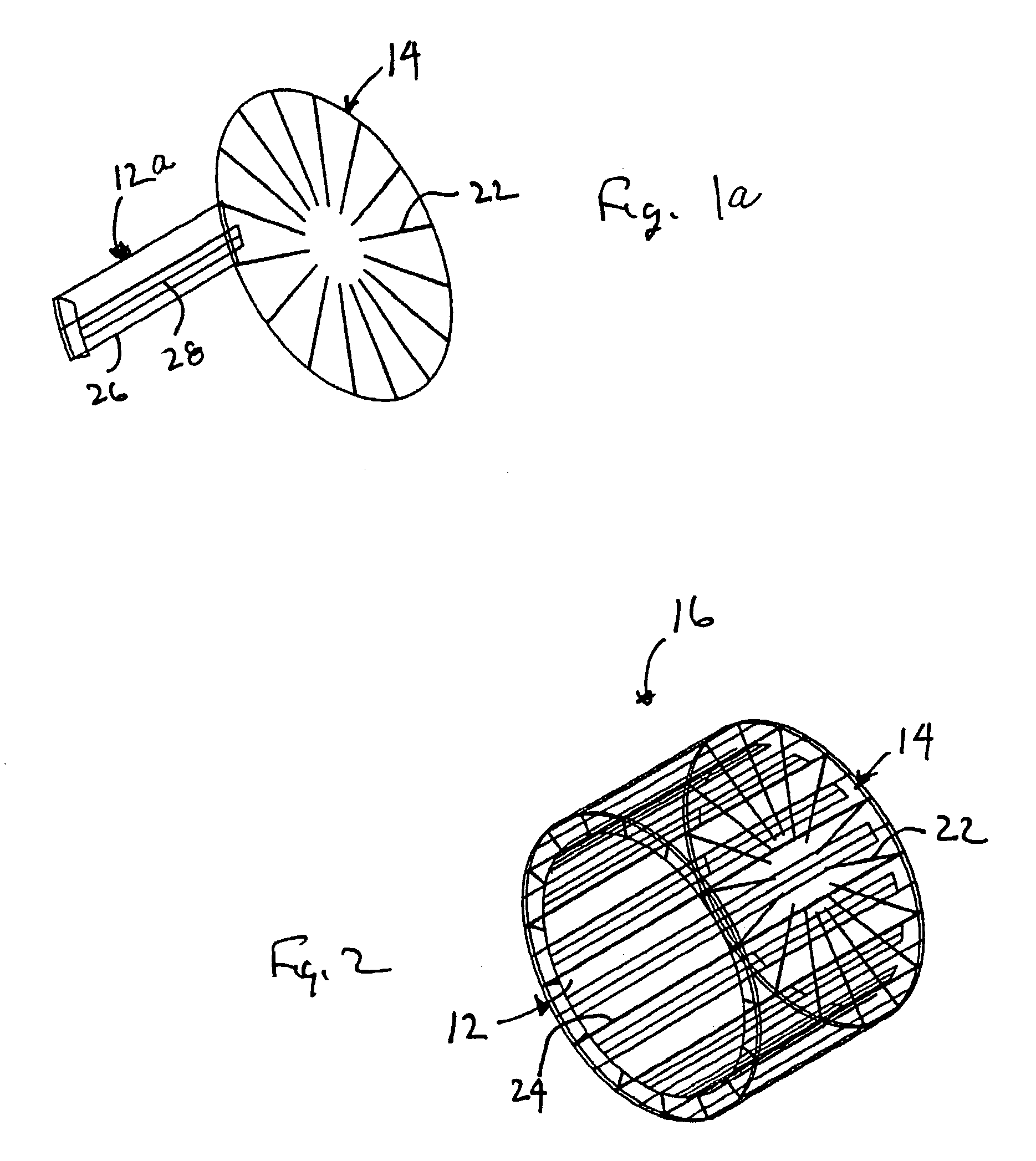
[0057]As shown in FIGS. 1a to 4, the coil at the heart of the present invention, is a transmit and / or receive coil that includes transmission line elements distributed in a circular, elliptical, or other geometrical arr...


PUM


Abstract

An magnetic resonance imaging system having a housing comprising a transmit and / or receive inductor system having a coil about the housing axis in proximity with the housing. The transmit and / or receive coil includes a series of electrical transmission line elements distributed with respect to the axis about the subject. Each transmission line element includes an outer conductor and an inner conductor spaced radially from the outer conductor relative to the axis. Capacitive elements are dispersed among the inner conductor and outer conductor. The coil includes capacitive elements connecting pairs of conductors. The capacitive elements may connect pairs of outer conductors or pairs of inner conductors.

Description

CROSS-REFERENCES TO RELATED APPLICATIONS[0001]The present application is a continuation application of Application No. 09 / 684,680, dated Oct. 7, 2000 for MAGNETIC RESONANCE IMAGING SYSTEM USING COILS HAVING PARAXIALLY DISTRIBUTED TRANSMISSION LINE ELEMENTS WITH OUTER AND INNER CONDUCTORS in the name of Patrick Ledden, now U.S. Pat. No. 6,501,274, which claims the benefit of U.S. Provisional Patent Application No. 60 / 159,662, dated Oct. 15, 1999 for HIGH RESOLUTION MAGNETIC RESONANCE IMAGING SYSTEM in the name of Patrick Ledden.STATEMENT REGARDING FEDERALLY SPONSORED RESEARCH OR DEVELOPMENT[0002]Not ApplicableREFERENCE TO A SEQUENCE LISTING, A TABLE, OR A COMPUTER PROGRAM LISTING COMPACT DISK APPENDIX[0003]Not ApplicableBACKGROUND OF THE INVENTION[0004]1. Field of the Invention[0005]The present invention relates to magnetic resonance imaging and, more particularly, to a high resolution magnetic resonance imaging system and to components thereof.[0006]2. Description of the Related Art...

Claims


Application Information

Patent Timeline
IPC IPC(8): G01V3/00G01R33/36
CPCG01R33/3453G01R33/3415G01R33/3657G01R33/365
Inventor LEDDEN, PATRICK
Owner NOVA MEDICAL
Why Eureka
Try Eureka