
Hybrid electric vehicle

Inactive Publication Date: 2006-02-28
GRUENWALD ROBERT +2
View PDF32 Cites 92 Cited by
  • Summary
  • Abstract
  • Description
  • Claims
  • Application Information

AI Technical Summary

Benefits of technology

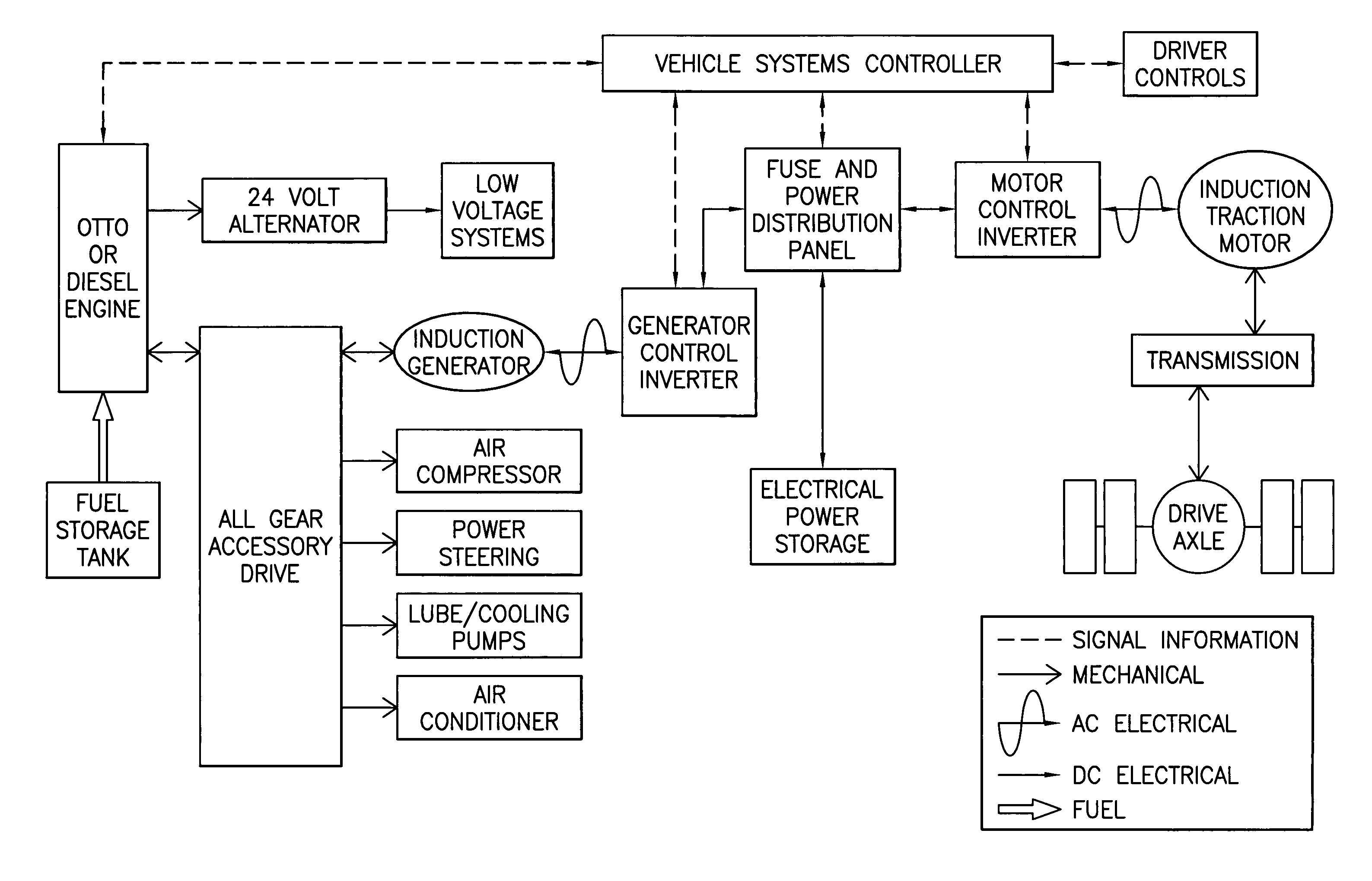
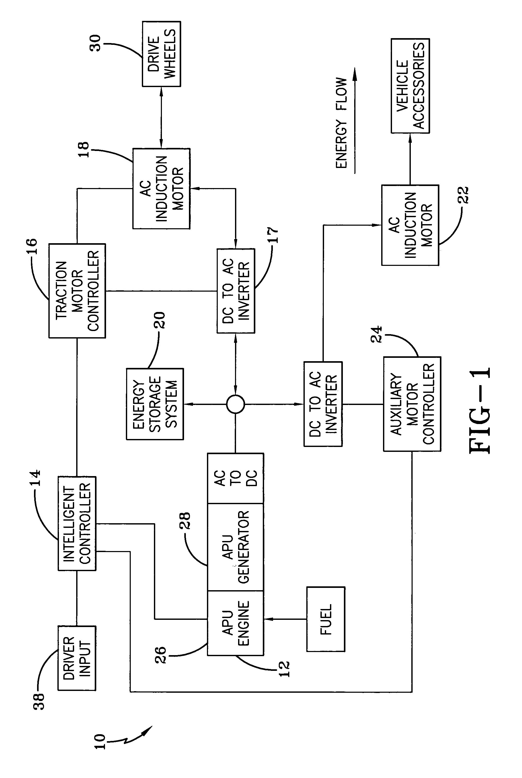
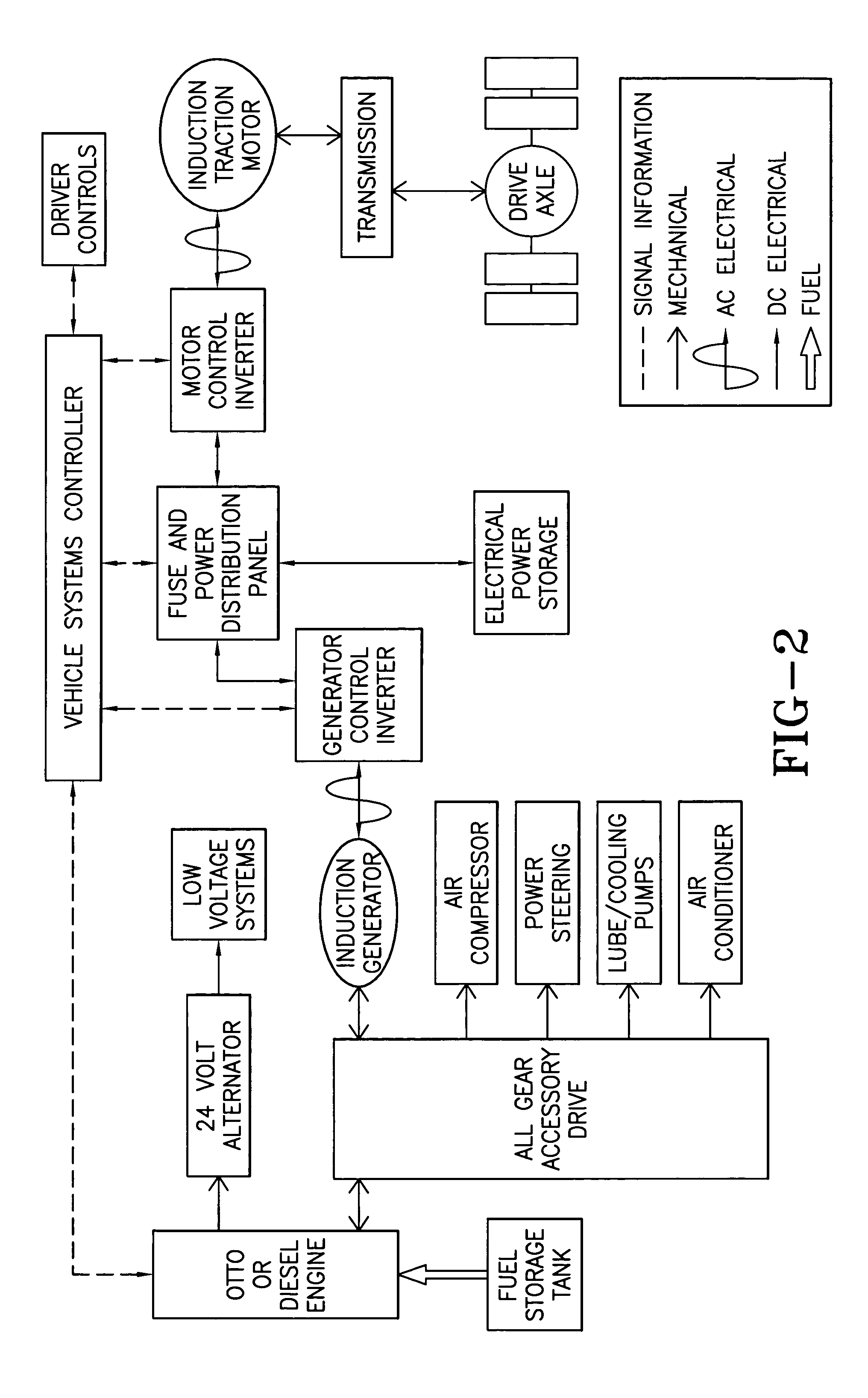
[0003]The HEV of the present invention uses an engine in combination with an electric motor. An energy storage device is also used to store energy for driving the electric motor. The engine, preferably in conjunction with a generator (for series drive embodiment or without for a parallel embodiment), and the energy storage device work in combination to provide energy for powering the vehicle motor. A series HEV uses an engine with a generator (APU / PPU) to supply electricity to the motor and the energy storage system. A parallel HEV has a direct mechanical connection between the engine and the wheels. The use of electric power substantially cuts down on chemical emissions and vastly improves fuel economy. Although HEVs have been previously known, the HEV technology of the present invention provides significant advantages of providing a viable HEV technology that allows for a high performance HEV with a unique power management and distribution system.
[0006]To store energy in a capacitor, voltage must be allowed to vary up and down. The greater the variation, the more energy can be stored and extracted. Electrical components designed for constant voltage (battery) operation cannot deliver rated power when operated below narrow voltage parameters or set-points. These components will also overheat if operated at low voltage for extended periods. Control strategies set to protect these components will cut back output, reducing vehicle performance or cause a safety trip out. When voltage begins to rise above the nominal set-point, as during regenerative braking, the battery system control strategy tapers back APU / PPU output and reduces regeneration effect. If voltage was allowed to rise as would be needed to properly charge a capacitor bank, the control system will cause an over-voltage trip out, or if left unchecked, will damage components.
[0010]One solution to overcoming the variable voltage requirement for capacitor storage is to install an electronic device between the drive system set up for batteries and the capacitor bank. This device, usually of the buck-boost design, would convert the variable voltage power required to take advantage of the capacitor storage to the near constant voltage needed by the battery traction system. In other words, make the capacitor look like a battery. This solution adds expense and complexity to the system and lowers the efficiency of a capacitor storage system.
[0014]One or more traction inverter(s) capable of delivering rated power at the low voltage set-point. Components sized to operate at the high voltage set-point. Control set up to eliminate instability at high voltage when using a low inductance motor.

Problems solved by technology

When one tries to replace batteries directly with capacitors, the battery control system strategy, which is designed to maintain the voltage level, cannot take full advantage of capacitor storage.
This under-utilization results in poor fuel economy, and for undersized APU / PPUs, poor vehicle performance will result.
Electrical components designed for constant voltage (battery) operation cannot deliver rated power when operated below narrow voltage parameters or set-points.
These components will also overheat if operated at low voltage for extended periods.
Control strategies set to protect these components will cut back output, reducing vehicle performance or cause a safety trip out.
When voltage begins to rise above the nominal set-point, as during regenerative braking, the battery system control strategy tapers back APU / PPU output and reduces regeneration effect.
If voltage was allowed to rise as would be needed to properly charge a capacitor bank, the control system will cause an over-voltage trip out, or if left unchecked, will damage components.
Even if the control over-voltage trip is removed, and components were sized to take the over-voltage condition, typical battery-type traction inverter drives produce unstable performance.
This is usually because inverters set up for battery systems are not equipped with the control logic and high-speed data sampling needed to deal with the transient current spikes developed by low-inductance motors operating at low motor speeds and at higher-than-rated voltage.
Furthermore, constant voltage APU / PPUs will not deliver power to the traction drive when voltage is above the nominal set-point.
This strategy does not allow it to share part of the initial load when accelerating the vehicle until voltage is near nominal.
This situation would require the APU / PPU to operate in an uneconomical peaking mode to finish the acceleration cycle or require a larger and proportionally costly and heavier capacitor bank.
This solution adds expense and complexity to the system and lowers the efficiency of a capacitor storage system.

Method used


Image

  • Hybrid electric vehicle
  • Hybrid electric vehicle
  • Hybrid electric vehicle

Examples


embodiment

Parallel Embodiment

[0074]FIG. 8 illustrates one embodiment of a parallel hybrid vehicle of the present invention. In contrast to those used in a battery hybrid system, the components and control strategies of the present invention have been designed to allow for a wide fluctuation in voltage without performance loss or nuisance trip outs. The system is designed to optimize APU / PPU performance with the least amount of capacitor bank requirement. The system does not require any device between the inverter drive and capacitor bank. In its parallel form, the three major components can be easily added or retrofitted to conventional engine drive systems to hold costs down. The parallel embodiment described below may be called an engine dominated, capacitor assist, parallel hybrid system.

[0075]The hardware for the parallel system preferably consists of three major components:

[0076]One or more low inductance traction motor(s), capable of delivering rated torque and power at the low voltage ...


PUM


Abstract

A hybrid electric propulsion system for powering a vehicle using a natural fuel engine and an electric motor. The hybrid electric vehicle is comprised of a drive train; an electric motor for driving the drive train; an auxiliary power unit (APU); an electric energy storage system electrically coupled to the electric motor; and wherein the auxiliary power unit and the electric energy storage system provide energy for powering the vehicle. An electric bus is directly connected to both the auxiliary power unit and the electric energy source and the voltage across the electric bus is substantially the same as the voltage across the electric energy source so that a change in voltage of the electric bus results in the same change to the voltage across the electric energy source. A power management controller is programmed to control output power of the power unit to maintain the energy storage system between a predetermined high voltage set-point and a predetermined low voltage set-point.

Description

[0001]This application is a Continuation of U.S. application Ser. No. 10 / 261,528, filed Oct. 1, 2002 now U.S. Pat. No. 6,651,759, which is a Continuation of U.S. application Ser. No. 09 / 558,048, filed Apr. 26, 2000 now U.S. Pat. No. 6,484,830, both of which are incorporated herein by reference.BACKGROUND AND SUMMARY OF THE INVENTION[0002]The present invention relates to an environmental friendly vehicle. More particularly, the present invention relates to a hybrid electric vehicle (HEV).[0003]The HEV of the present invention uses an engine in combination with an electric motor. An energy storage device is also used to store energy for driving the electric motor. The engine, preferably in conjunction with a generator (for series drive embodiment or without for a parallel embodiment), and the energy storage device work in combination to provide energy for powering the vehicle motor. A series HEV uses an engine with a generator (APU / PPU) to supply electricity to the motor and the energ...

Claims


Application Information

Patent Timeline
IPC IPC(8): B60K6/04B60K6/46
CPCB60K6/46B60L1/02B60L3/12B60L7/14B60L11/005B60L11/126B60L11/16B60L11/1868B60W10/06B60W10/08B60W10/26B60W10/30B60W20/00B60L1/003Y02T10/7066B60L2210/40B60L2220/12B60L2240/12B60L2240/36B60L2240/421B60L2240/423B60L2240/441B60L2240/445B60L2240/662B60L2250/10Y02T10/6217Y02T10/6286Y02T10/7005Y02T10/7022Y02T10/7291Y02T90/16Y02T10/7241B60L50/40B60L50/62B60L50/30B60L58/20Y02T10/62Y02T10/70Y02T10/72B60W20/13
Inventor GRUENWALD, ROBERTMAJOR, JEFF T.PALUMBO, ANTHONY J.
Owner GRUENWALD ROBERT
Learn More