
Method of producing a dopant gas species

Active Publication Date: 2006-02-14
APPLIED MATERIALS INC
View PDF2 Cites 5 Cited by
  • Summary
  • Abstract
  • Description
  • Claims
  • Application Information

AI Technical Summary

Benefits of technology

[0010]Use of a bromine gas to create volatile bromide, rather than using chlorides and fluorides previously suggested, has been found to have many benefits, as follows.
[0013](3) Bromine is less reactive than fluorine making it easier to handle with less safety precautions to consider. Also, its higher vapour pressure means less condensation. Thus transporting the bromine vapour from bottle to reaction chamber is easier.
[0018]Preferably, the method further comprises regulating the supply of gaseous bromine to the element. This, in turn, leads to a regulation of the rate of ion production in the ionisation chamber and hence the ion beam current. Moreover, this method of control is far more responsive than the prior art method of varying the temperature of an oven.

Problems solved by technology

However, many of the dopants are metals with low vapour pressures meaning the oven must be operated at high temperatures to produce the required vapour.
Adjusting the beam current requires an adjustment of the temperature of the oven and control is therefore limited by the thermal response time of the oven (as much as 30 minutes).
Moreover, control is unpredictable because the true temperature of the contents of the oven cannot be known precisely.
The low vapour pressure of indium fluoride poses another problem in the condensation of the vapour so produced.
Thus, transport of the vapour becomes difficult.
These methods of producing a dopant gas species pose a problem because they show great sensitivity to variations in temperature, i.e. a graph showing how their vapour pressure varies with temperature is particularly steep around the operating temperature of the ovens.
As a result, there is a burden in that fine control of the oven temperature is necessary.

Method used


Image

  • Method of producing a dopant gas species
  • Method of producing a dopant gas species
  • Method of producing a dopant gas species

Examples


example

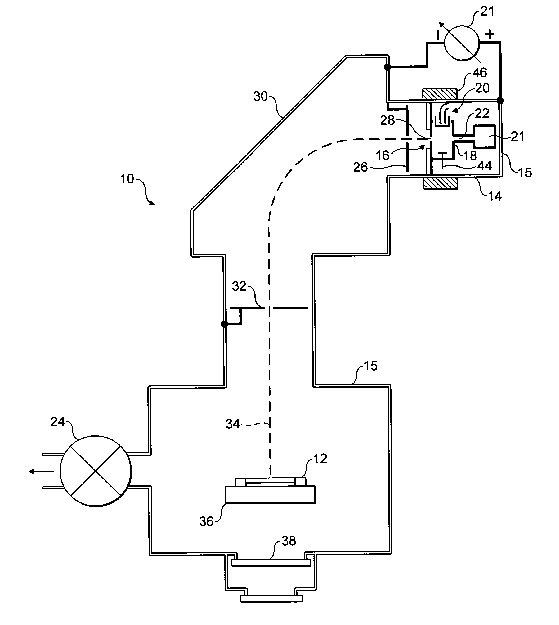
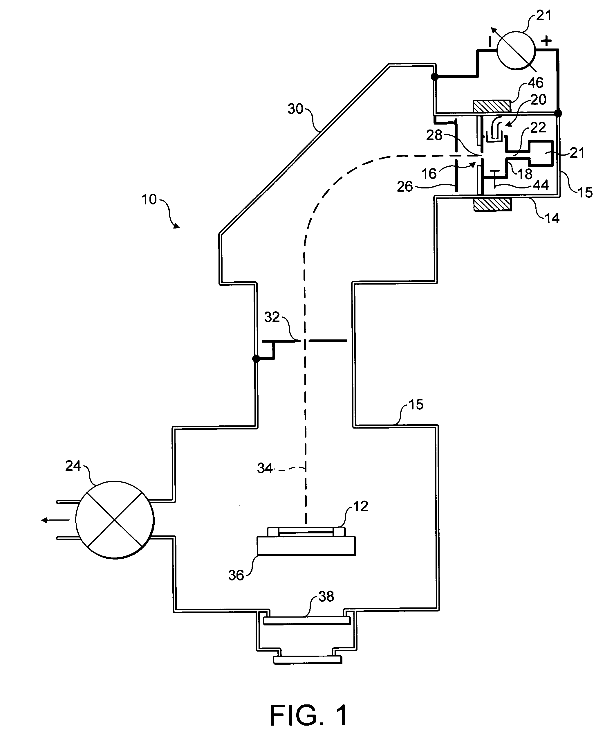
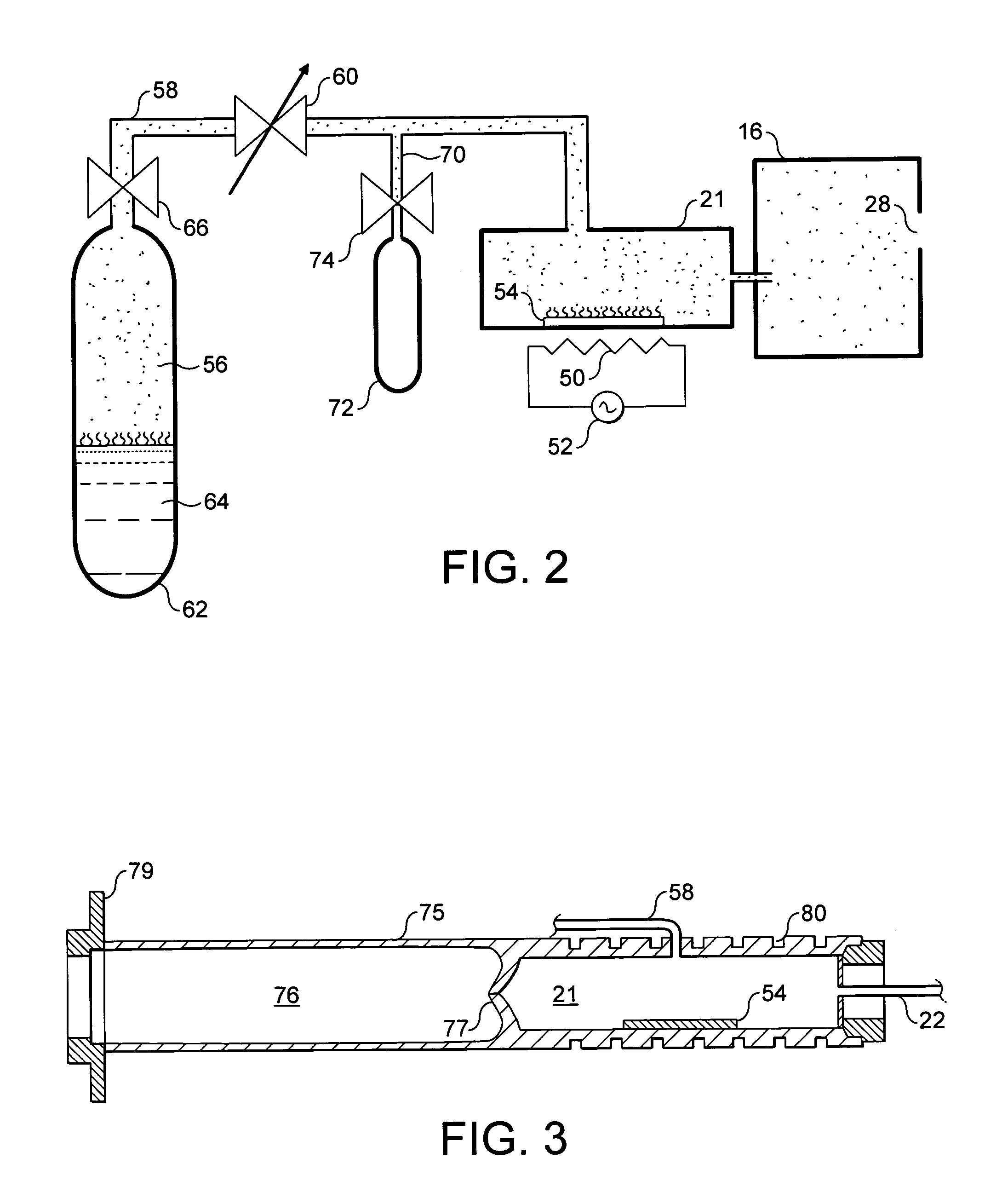
[0054]By way of example, FIG. 4 shows the results of an experiment conducted using an ion source 14 exemplified by FIGS. 2 and 3. In the experiment, 100 g of bromine liquid 64 was placed in a stainless steel container 62. The flow of bromine vapour 56 was regulated at 0.24 sccm, which has been found to optimise the production of In++ ions.

[0055]The oven 21 contained 8 g of indium metal strip 54 and was heated to 380° C. The arc chamber 16 was operated to arc at 75V / 1A. An extraction current of 12 mA was used with an extraction voltage of 50 kV. This extraction voltage is generally low, but allowed the observation of In+ ions. These conditions produced an In++ beam current of 1 mA, as shown in FIG. 4 that shows the beam currents of the different ions extracted from the arc chamber 16. During implantation, the bromine ions and undesired indium ions may be rejected using the mass analysing magnet 30.

[0056]In addition, the effect of varying the oven temperature on a 1 mA In++ beam was i...


PUM


Abstract

This invention relates to a method of producing a dopant gas species containing a required dopant element for implanting in a target and to an ion source for implementing such a method. In particular, although not exclusively, this invention relates to producing dopant ions for implanting in semiconductor wafers using an ion implanter. The present invention provides a method of producing a dopant gas species containing a required dopant element for implanting in a target, the method comprising: exposing a source mass of the element to gaseous bromine and element react to form a reactant product, and ionising the reactant product to produce ions of the dopant gas species.

Description

FIELD OF THE INVENTION[0001]This invention relates to a method of producing a dopant gas species containing a desired dopant element for implanting in a target and to an ion source for implementing such a method. In particular, although not exclusively, this invention relates to producing dopant ions for implanting in semiconductor wafers using an ion implanter.BACKGROUND OF THE INVENTION[0002]The semiconductor industry has a requirement for the production of semiconductor devices that is most often met by fabrication of arrays of many devices on a single wafer. The semiconductor devices often require doping to very fine tolerances to achieve desired characteristics. Such doping may be performed using an ion implanter that comprises an ion source to generate ions corresponding to, or containing, the required dopant. Optics then form the ions into a focussed ion beam that is incident upon the wafer. Control of the ion beam (e.g. beam current, ion content, energy, size, scanning, etc....

Claims


Application Information

Patent Timeline
IPC IPC(8): H01J37/317H01J49/10
CPCH01J27/022H01J37/08H01J37/3171H01J2237/083H01J2237/061H01J2237/0815B01J8/18B01J12/00B01J19/08
Inventor RYDING, GEOFFREYSATOH, SHU
Owner APPLIED MATERIALS INC
Learn More