
Method for aluminide coating a hollow article

a hollow article and aluminide coating technology, applied in the direction of solid-state diffusion coating, stators, machines/engines, etc., can solve the problems of difficult to achieve uniform coating of the exterior and interior surfaces of the hollow sections, difficult control of powder chemistry and handling, and difficult to achieve uniform coating. uniform distribution, less environmental protection, and less uniform coating distribution

Active Publication Date: 2006-01-24
GENERAL ELECTRIC CO
View PDF9 Cites 14 Cited by
  • Summary
  • Abstract
  • Description
  • Claims
  • Application Information

AI Technical Summary

Benefits of technology

[0007]The present invention provides a method for producing an aluminide coating on the interior and the exterior surfaces of a hollow article. The technique is particularly useful in the refurbishment of hollow articles that have previously been in service. This approach achieves a robust, sufficiently thick, reasonably uniform coating over the interior surfaces and the exterior surfaces.
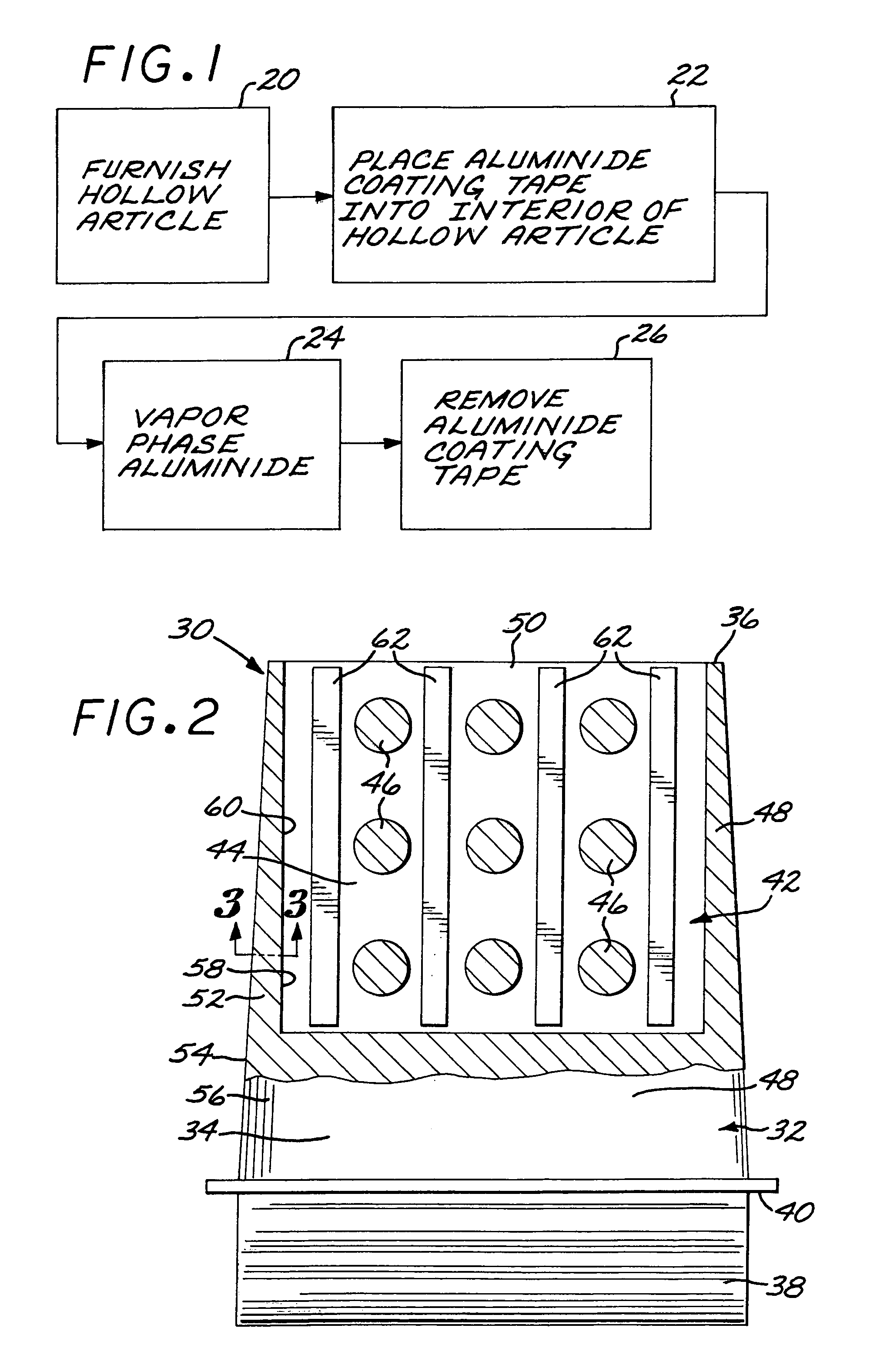
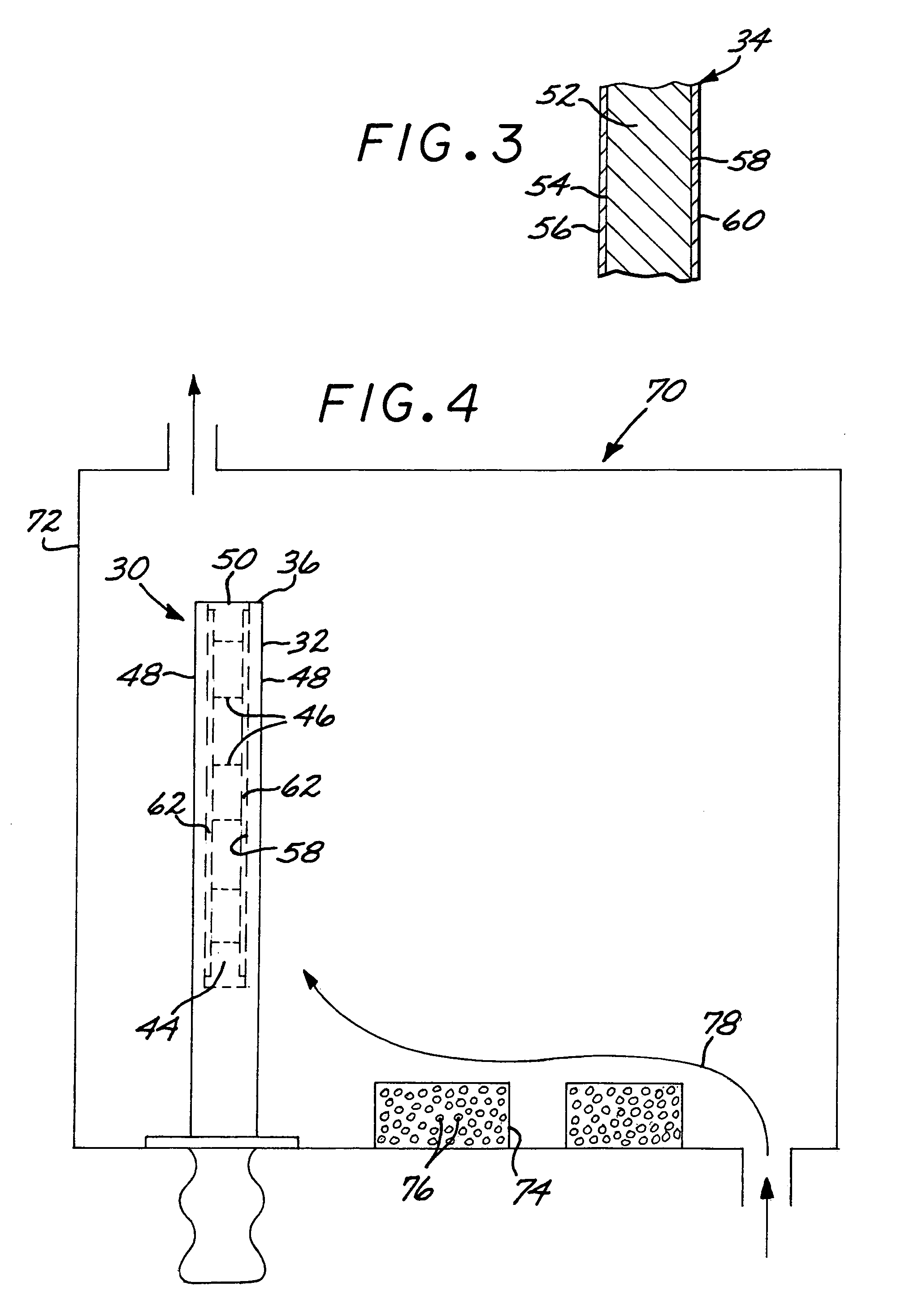
[0012]Prior to developing the present approach, attempts were made to refurbish the aluminide coating using only the vapor phase aluminiding process. The result was that the aluminum vapor did not penetrate into the interior of the hollow cavity to deposit a sufficiently thick and uniform coating. The coating tape inserted into the hollow interior, in addition to the vapor phase aluminiding using a separate, external source, results in a sufficiently thick and uniform aluminide coating over the exterior surface of the airfoil and the interior surface of the hollow portion of the airfoil. The coating tape provides a dependable, convenient source of aluminide vapor in the interior of the hollow article. A powder source is not used within the interior of the hollow article because it is more difficult to control the powder chemistry and to handle the powder, there is a less uniform coating distribution produced with the powder source, the powder source uses a different optimum coating temperature, and the powder-source approach is less environmentally friendly, as compared with the use of the aluminide coating tape.

Problems solved by technology

In current engines, the turbine vanes and blades are made of nickel-based superalloys, and can operate at temperatures of up to about 1800–2100° F. At these temperatures, the components are subject to damage by oxidation and corrosion.
The uniform coating of the exterior and interior surfaces of the hollow sections is difficult to achieve, particularly where there is no possibility for an end-to-end flow through of a coating vapor and particularly in refurbishment operations after the turbine blades or vanes have been used in service and are returned for refurbishment.

Method used


Image

  • Method for aluminide coating a hollow article
  • Method for aluminide coating a hollow article
  • Method for aluminide coating a hollow article

Examples


Embodiment Construction

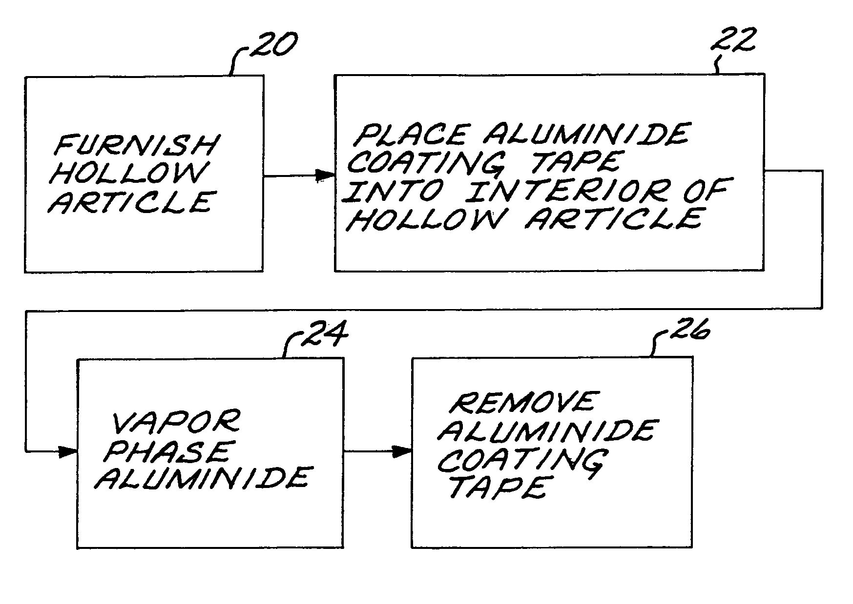
[0018]FIG. 1 depicts a preferred approach for producing an aluminide coating on a hollow article. The hollow article is furnished, step 20. FIG. 2 illustrates a preferred form of an article 30 that may be processed using the present approach. In this case, the article 30 is a gas turbine blade 32. The gas turbine blade 32 includes an airfoil section 34 having a blade tip 36, an attachment 38 in the form of a dovetail or fir-tree section, and a platform 40 extending laterally outwardly from a location between the airfoil section 34 and the attachment 38.

[0019]The gas turbine blade 32 is preferably made of a single piece of a metallic alloy, more preferably a nickel-base alloy, and most preferably a nickel-base superalloy. As used herein, “nickel-base” means that the composition has more nickel present than any other element. The nickel-base superalloys are typically of a composition that is strengthened by the precipitation of gamma-prime phase or a related phase. A typical nickel-ba...


PUM

PropertyMeasurementUnit
temperatureaaaaaaaaaa
temperaturesaaaaaaaaaa

Abstract

An aluminide coating is produced on a hollow article by furnishing an article having a hollow interior and an access opening to the hollow interior, placing an aluminide coating tape into the hollow interior through the access opening, and vapor phase aluminiding the hollow article using an external aluminum vapor source in addition to the aluminide coating tape.

Description

[0001]This invention relates to the application of aluminide coatings to articles and, more particularly, to the aluminide coating of hollow articles.BACKGROUND OF THE INVENTION[0002]In an aircraft gas turbine (jet) engine, air is drawn into the front of the engine, compressed by a shaft-mounted compressor, and mixed with fuel. The mixture is burned, and the hot combustion gases are passed through a turbine mounted on the same shaft. The flow of combustion gas turns the turbine by impingement against an airfoil section of the respective turbine blades and vanes, which turns the shaft and provides power to the compressor. The hot exhaust gases flow from the back of the engine, driving it and the aircraft forward.[0003]The hotter the combustion and exhaust gases, the more efficient is the operation of the jet engine. There is thus an incentive to raise the combustion and exhaust gas temperatures. The maximum temperature of the combustion gases is normally limited by the materials used...

Claims


Application Information

Patent Timeline
Patent Type & Authority Patents(United States)
IPC IPC(8): B05D7/22C23C16/00F01D5/18C23C10/04C23C10/08C23C10/28C23C10/30C23C16/448F01D5/28F01D9/02
CPCC23C10/08F01D5/288C23C10/28Y02T50/671Y02T50/60
Inventor HENG, YOW KWOKNAM, CHEN KENGLANGLEY, NIGEL BRIAN THOMASGAEWSKY, JANET ELIZABETH
Owner GENERAL ELECTRIC CO
Learn More