
Scalable lead zirconium titanate (PZT) thin film material and deposition method, and ferroelectric memory device structures comprising such thin film material

Inactive Publication Date: 2006-01-10
ENTEGRIS INC
View PDF14 Cites 15 Cited by
  • Summary
  • Abstract
  • Description
  • Claims
  • Application Information

AI Technical Summary

Benefits of technology

[0046]Correlative Materials or ProcessingPZT PropertiesRequirementsBasic properties:Ferroelectric polarizationFilm Pb concentration > threshold level;PSW > 20 μC/cm2operation on A/B plateau above the kneeregion, and with temperature, pressure andgas phase A/B concentration ratio defined byplateau effect determinationLeakage current densityFilm Pb concentration within a range (betweenJ < 10−5 A/cm2the minimum and maximum) on the A/Bat operating voltageplateau, and with temperature, pressure andgas phase A/B concentration ratio definedby plateau effect determinationDielectric relaxationZr/Ti ratio < 45/55For characteristic J−n ∝Deposition P > 1.8 torrlog (time), n > 0.5and J < 1% ferroelectricswitching current from0–100 ns.RetentionOperation wi

Problems solved by technology

Pt / SBT / Pt capacitors, for example, have been shown to have excellent fatigue and retention characteristics, although processing temperatures in excess of 750° C. pose integration issues.
For PZT, phase-pure thin films can be deposited at temperatures in the 450–650° C. range, although Pt / PZT / Pt capacitors are known to suffer from poor fatigue and retention.
SBT, however, is handicapped by a low value of switched ferroelectric polarization (Psw), typically less than 25 μC / cm2.
Furthermore, the thermal processing (800° C.) required for improvement of thin film properties is considered severe and undesirable.

Method used


Image

  • Scalable lead zirconium titanate (PZT) thin film material and deposition method, and ferroelectric memory device structures comprising such thin film material
  • Scalable lead zirconium titanate (PZT) thin film material and deposition method, and ferroelectric memory device structures comprising such thin film material
  • Scalable lead zirconium titanate (PZT) thin film material and deposition method, and ferroelectric memory device structures comprising such thin film material

Examples


example 1

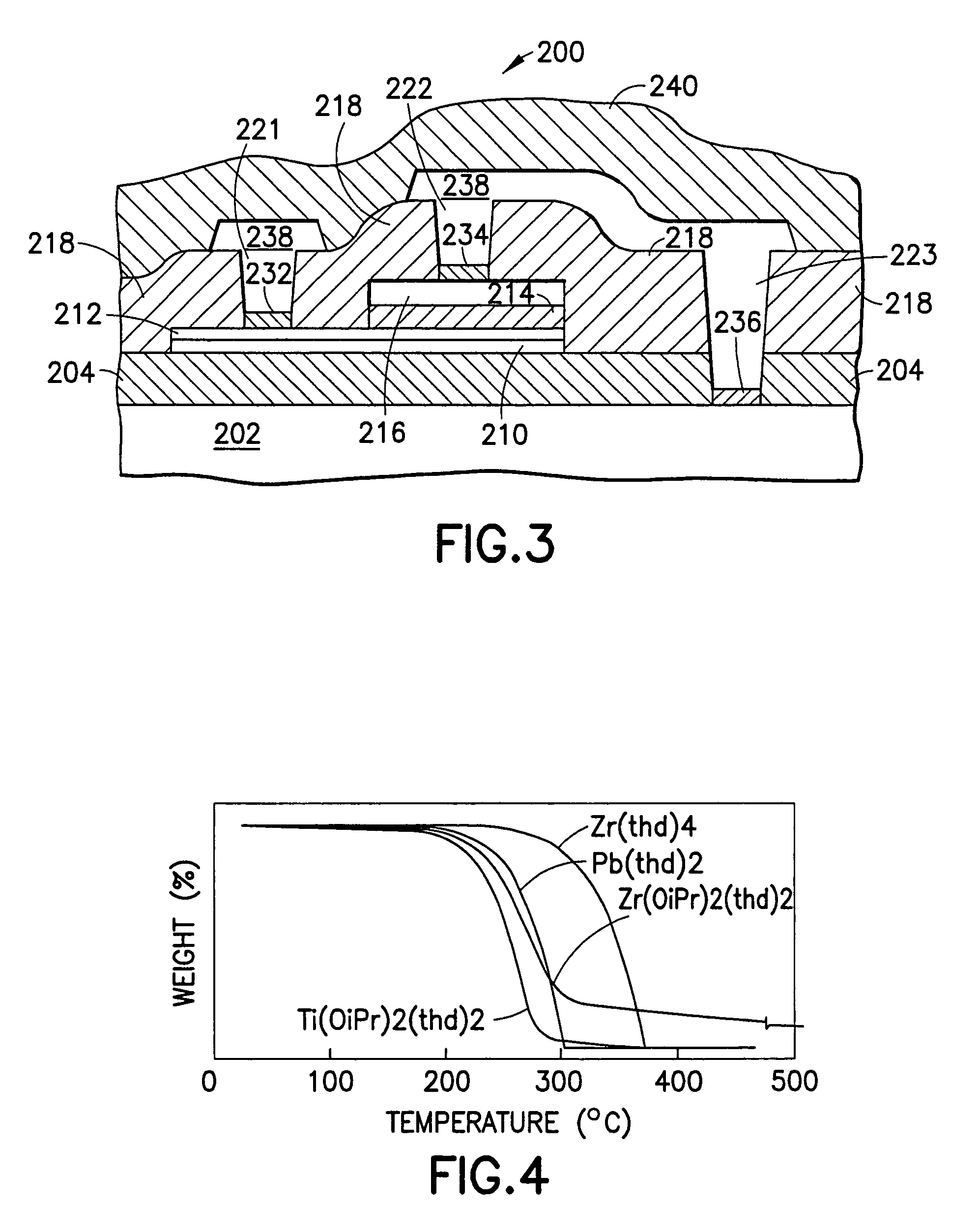
[0112]The lead precursor chosen was lead bis(2,2,6,6-tetramethyl-3,5-heptanedionate) [Pb(thd)2]. This compound has no appreciable vapor pressure at room temperature, which makes it much safer to handle than tetra-alkyl lead reagents. However, the low volatility of Pb(thd)2 (0.05 Torr at 180° C.) requires the use of liquid precursor delivery. Titanium bis(isopropoxide)bis(2,2,6,6-tetramethyl-3,5-heptanedionate) [Ti(O-i-Pr)2(thd)2] was used as the titanium precursor. Zirconium tetrakis(2,2,6,6-tetramethyl-3,5-heptanedionate) [Zr(thd)4] was used as the Zr source reagent. These compounds are extremely soluble in organic media and no possible detrimental ligand exchange occurs since the titanium atom is coordinatively saturated.

[0113]The following process conditions were applied:

[0114]

Operating ParameterProcess ConditionSubstrate temperature550~610° C.Bottom electrodeIr / SiO2 / SiTotal reactor pressure1~10 TorrReactor wall temperature~210° C.Carrier Ar flow~200 sccmO2 flow500 sccmN2O flow50...

example 2

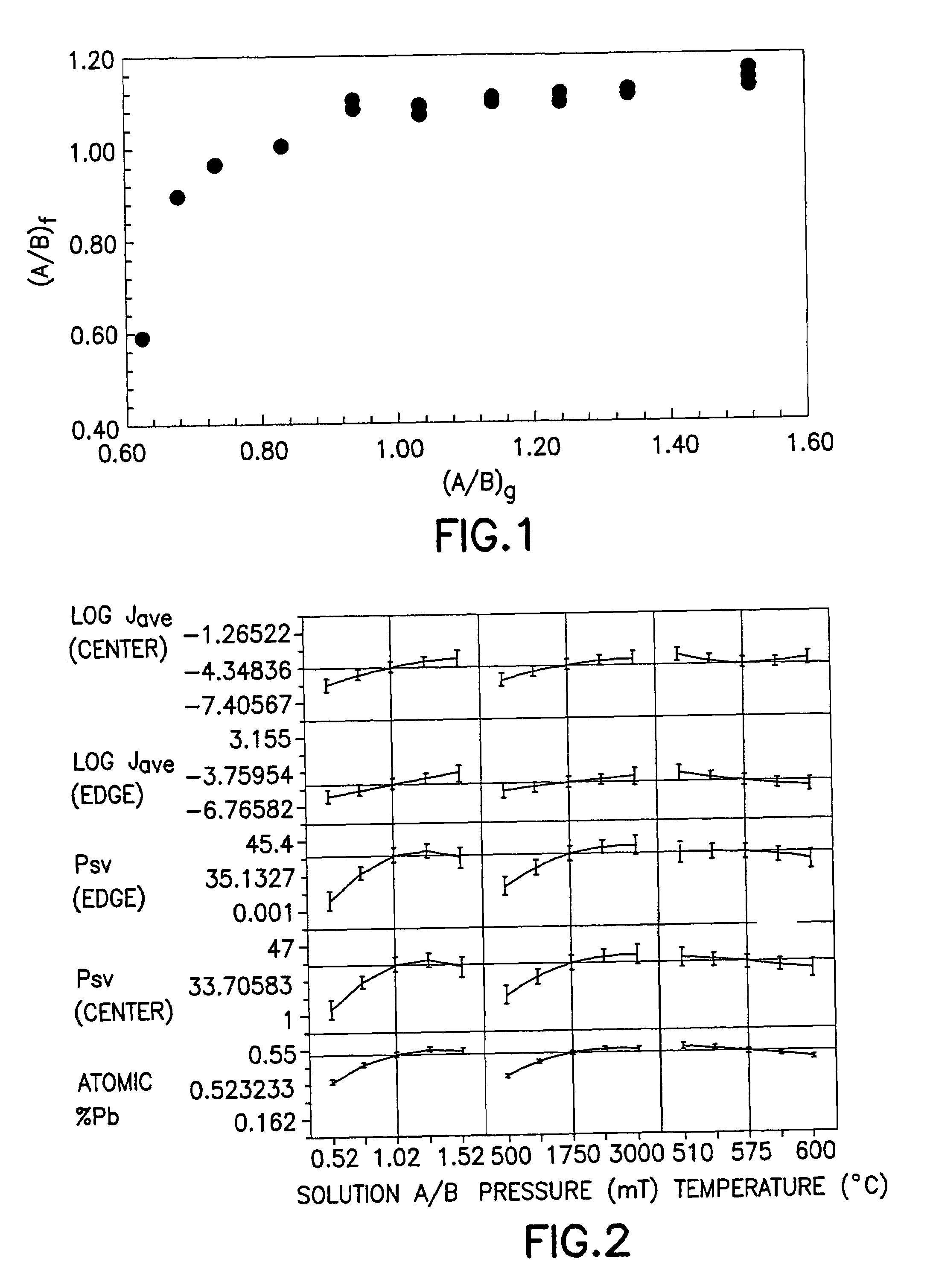
[0117]Solutions with a range of different Pb / (Zr+Ti) ratios were used over a series of deposition runs. This ratio is hereafter defined as (A / B)g, denoting the conventional assignment of Pb to the “A” site, and Zr and Ti each to the “B” site in the perovskite cell, ABO3. The subscript g denotes the gas-phase concentration in the reaction chamber, while (A / B)f denotes the equivalent ratio in the film.

[0118]The gas phase ratio of Zr / (Zr+Ti) was held constant at 0.612. Under the conditions given above in Example 1 and for the specific CVD reactor employed, the gas phase ratio of Zr / (Zr+Ti)=0.612 resulted in films with Zr / Ti˜40 / 60, which for bulk materials yielded a tetragonal crystal structure and ferroelectric properties. This is a common composition chosen for FeRAM applications because of its high Pr and the relative ease in forming the perovskite phase for lower Zr / Ti ratios.

[0119]Next, a series of PZT films was deposited with fixed deposition time, under the process conditions set...

example 3

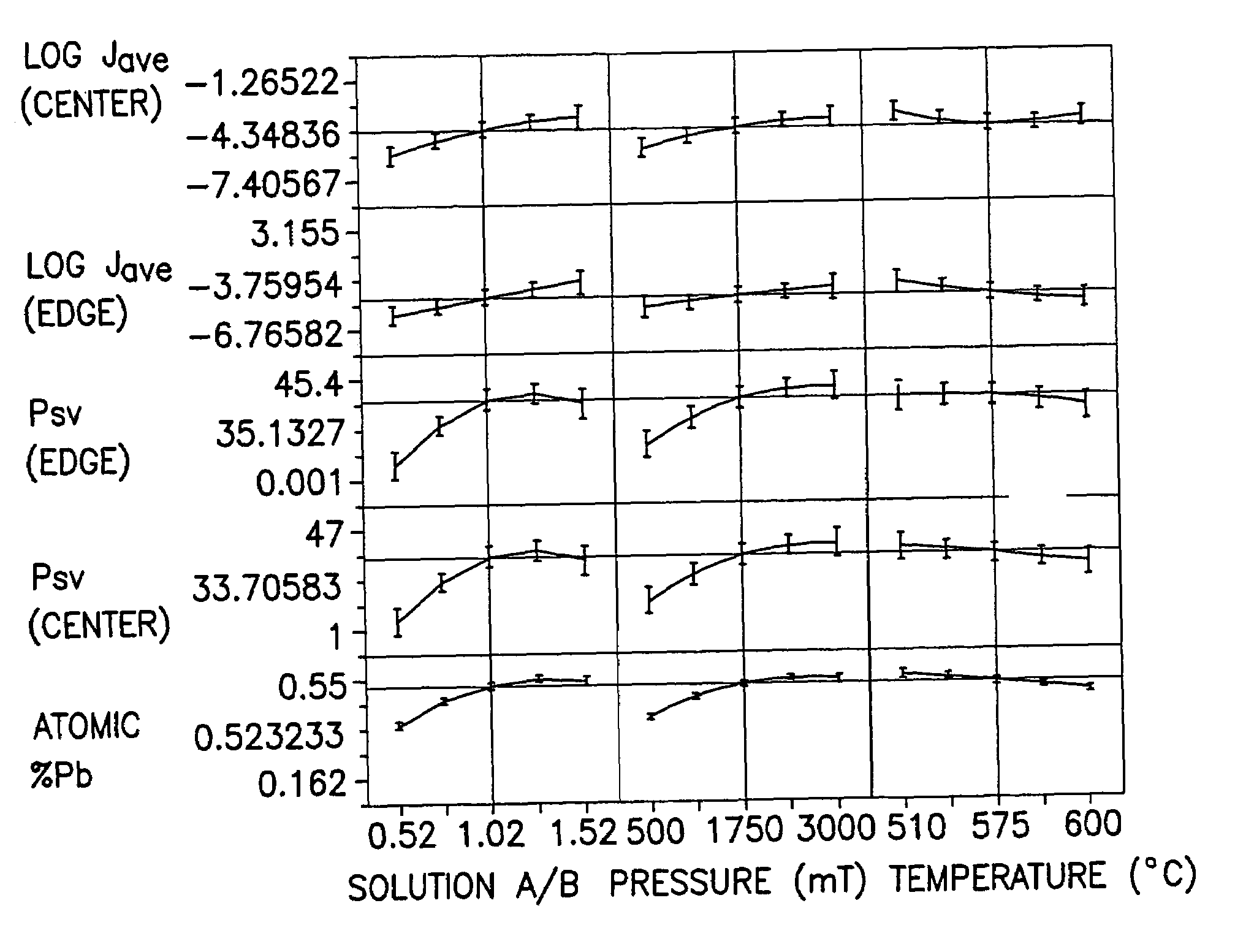
[0130]A central-composite-design experiment was used to probe a large volume of process space and assess interactions between principal process variables. Deposition temperature (550, 575, 600° C.) and pressures (500, 1750, 3000 mTorr) were independently varied at five different values of (A / B)g: (0.53, 0.73, 0.93, 1.13, 1.53). A constant deposition time of 1660 seconds was used.

[0131]Compositionally, a plateau onset in (A / B)f was observed at (A / B)g=0.93. For a given pressure, film lead content was observed to decrease with increased deposition temperature. Furthermore, incorporation efficiencies of both lead and titanium decreased with increasing (A / B)g for all temperatures.

[0132]Electrically, the best samples arose from the conditions at the center of the design (575° C., 1.75 Torr, (A / B)g˜1). Most of the good samples displayed a (−) voltage offset. There was no appreciable center-to-edge (wafer) effect. Leakage seemed to behave better for lower Pb and for thicker samples (˜130 nm...


PUM

PropertyMeasurementUnit
Temperatureaaaaaaaaaa
Fractionaaaaaaaaaa

Abstract

A novel lead zirconium titanate (PZT) material having unique properties and application for PZT thin film capacitors and ferroelectric capacitor structures, e.g., FeRAMs, employing such thin film material. The PZT material is scalable, being dimensionally scalable, pulse length scalable and / or E-field scalable in character, and is useful for ferroelectric capacitors over a wide range of thicknesses, e.g., from about 20 nanometers to about 150 nanometers, and a range of lateral dimensions extending to as low as 0.15 μm. Corresponding capacitor areas (i.e., lateral scaling) in a preferred embodiment are in the range of from about 104 to about 10−2 μm2. The scalable PZT material of the invention may be formed by liquid delivery MOCVD, without PZT film modification techniques such as acceptor doping or use of film modifiers (e.g., Nb, Ta, La, Sr, Ca and the like).

Description

[0001]This is a continuation of U.S. application Ser. No. 09 / 251,890, Feb. 19, 1999 now U.S. Pat. No. 6,316,797.BACKGROUND OF THE INVENTION[0002]1. Field of the Invention[0003]This invention relates generally to a novel lead zirconium titanate (PZT) material having unique properties and application for PZT thin film capacitors, as well as to a deposition method for forming PZT films of such material, and ferroelectric capacitor structures employing such thin film material.[0004]2. Description of the Related Art[0005]There is a major effort by semiconductor companies throughout the world to commercialize high dielectric constant and ferroelectric thin films in advanced dynamic random access memories (DRAMs) and ferroelectric random access memories (FeRAMs), respectively.[0006]While the majority of current efforts are directed to the commercial development of relatively large capacitors (e.g. 5 μm2 area), the ultimate goal is to adapt ferroelectric random access memory technology for ...

Claims


Application Information

Patent Timeline
IPC IPC(8): C23C16/06C23C16/00C04B35/491C23C16/40H01B3/00H01B3/12H01G4/12H01L21/314H01L21/316H01L21/3205H01L21/768H01L21/8242H01L21/8246H01L23/52H01L23/522H01L27/105H01L27/115
CPCC04B35/491C07F7/003C23C16/409C07C49/92H01L21/31691H01L27/11502H01L27/11507H01L28/55H01G4/1245C04B2235/441C04B2235/449C04B2235/963H01G4/33H01L21/02197H01L21/02205H01L21/02271H10B53/30H10B53/00H01L27/105
Inventor VAN BUSKIRK, PETER C.ROEDER, JEFFREY F.BILODEAU, STEVEN M.RUSSELL, MICHAEL W.JOHNSTON, STEPHEN T.VESTYCK, DANIEL J.BAUM, THOMAS H.
Owner ENTEGRIS INC
Learn More