
Strengthened bond coats for thermal barrier coatings

a technology of bond coats and coatings, applied in the direction of magnetic recording, liquid fuel engine components, record information storage, etc., can solve the problems of thermally and chemically hostile operating environment of gas turbine engines, components formed from such alloys often cannot withstand long service exposures, and gradually deplete aluminum from the bond coat, so as to achieve the effect of increasing the strength of the bond coa

Inactive Publication Date: 2005-12-27
GENERAL ELECTRIC CO
View PDF33 Cites 41 Cited by
  • Summary
  • Abstract
  • Description
  • Claims
  • Application Information

AI Technical Summary

Benefits of technology

[0019]The embodiments this invention provide several benefits. The inclusion of relatively fine dispersed particles (i.e., up to about 2 microns) of a substantially insoluble bond coat strengthening compound can strengthen the bond coat so as to limit bond coat ratcheting or rumpling and thus prevent subsequent thermal barrier coating spallation. The dispersion of these relatively fine particles particularly especially allows for increased strengthening of bond coats comprising aluminide diffusion coating materials, or combinations thereof with overlay coating materials. The dispersed relatively fine particles can also be formed from bond coat strengthening compounds that are a substantially oxidatively non-reactive so that the oxidation resistance of the strengthened bond coat, especially strengthened bond coats formed from aluminide diffusion coating materials, is also not degraded.

Problems solved by technology

The operating environment within a gas turbine engine is both thermally and chemically hostile.
Significant advances in high temperature alloys have been achieved through the formulation of iron, nickel and cobalt-base superalloys, though components formed from such alloys often cannot withstand long service exposures if located in certain sections of a gas turbine engine, such as the turbine, combustor and augmentor.
During exposure to the oxidizing conditions within a gas turbine engine, bond coats inherently continue to oxidize over time at elevated temperatures, which gradually depletes aluminum from the bond coat and increases the thickness of the oxide scale.
As a result of the thermal expansion mismatch between the bond coat and the oxide scale, as well as the scale growth process and relative mechanical properties at temperature, thermal cycling leads to stresses that cause ratcheting or rumpling of the scale into the bond coat.
Once spallation has occurred, the component can deteriorate rapidly, and therefore must be refurbished or scrapped at considerable cost.
However, inoculating the bond coat surface prevents or at least limits the type of surface preparation that the bond coat can undergo prior to deposition of the thermal barrier coating.
However, codepositing according to the Gupta et al method cannot readily control the types and morphology of oxides incorporated into the bond coat.
In the Wustman et al system, the large particles present can potentially allow relatively high surface areas to be exposed to the oxidizing atmosphere, thus causing rapid internal oxidation, and subsequently poor oxidation resistance.
Control of the particle distribution can be difficult or potentially impossible using the Wustman et al system.
There is also the potential inability to create a distribution of extremely fine (i.e., nanometer to micron size) particles in the Wustman et al system.
However, oxidatively reactive elements are difficult to incorporate and control in diffusion coatings.

Method used


Image

  • Strengthened bond coats for thermal barrier coatings
  • Strengthened bond coats for thermal barrier coatings

Examples


Embodiment Construction

[0022]As used herein, the term “thermal barrier coating” refers to those coatings that are capable of reducing heat flow to the underlying metal substrate of the article, i.e., form a thermal barrier and usually having a melting point of at least about 2000° F. (1093° C.), typically at least about 2200° F. (1204° C.), and more typically in the range of from about 2200° to about 3500° F. (from about 12040 to about 1927° C.). Suitable thermal barrier coatings for use herein can comprise a variety of ceramic materials, including aluminum oxide (alumina), i.e., those compounds and compositions comprising Al2O3, including unhydrated and hydrated forms, various zirconias, in particular chemically phase-stabilized zirconias (i.e., various metal oxides such as yttrium oxides blended with zirconia), such as yttria-stabilized zirconias, ceria-stabilized zirconias, calcia-stabilized zirconias, scandia-stabilized zirconias, magnesia-stabilized zirconias, ytterbia-stabilized zirconias as well as...


PUM

PropertyMeasurementUnit
particle sizeaaaaaaaaaa
volume percentaaaaaaaaaa
particle sizeaaaaaaaaaa

Abstract

A strengthened bond coat for improving the adherence of a thermal barrier coating to an underlying metal substrate to resist spallation without degrading oxidation resistance of the bond coat. The bond coat comprises a bond coating material selected from the group consisting of overlay alloy coating materials, aluminide diffusion coating materials and combinations thereof. Particles comprising a substantially insoluble bond coat strengthening compound and having a relatively fine particle size of about 2 microns or less are dispersed within at least the upper portion of the bond coat in an amount sufficient to impart strengthening to the bond coat, and thus limit ratcheting or rumpling thereof.

Description

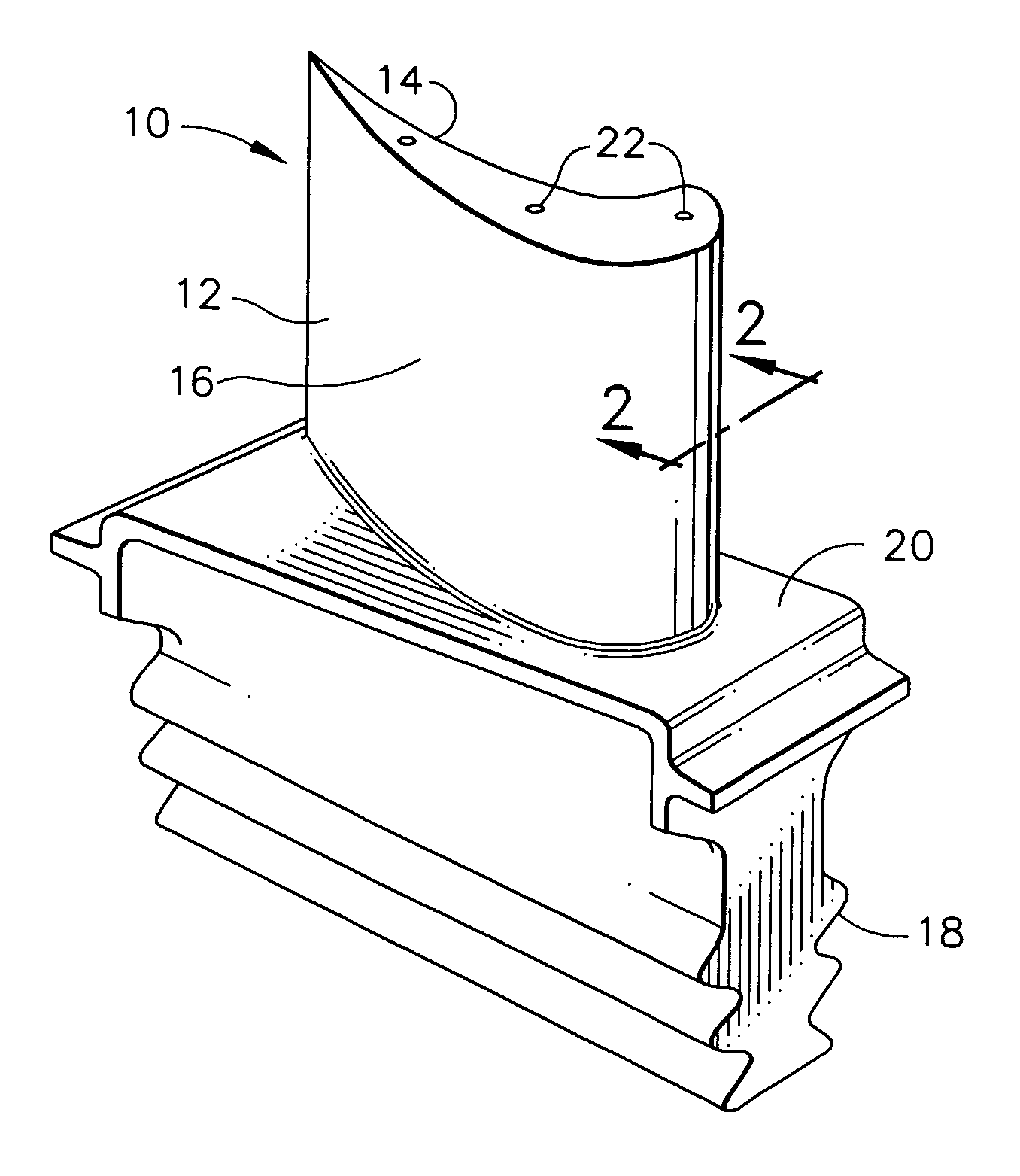
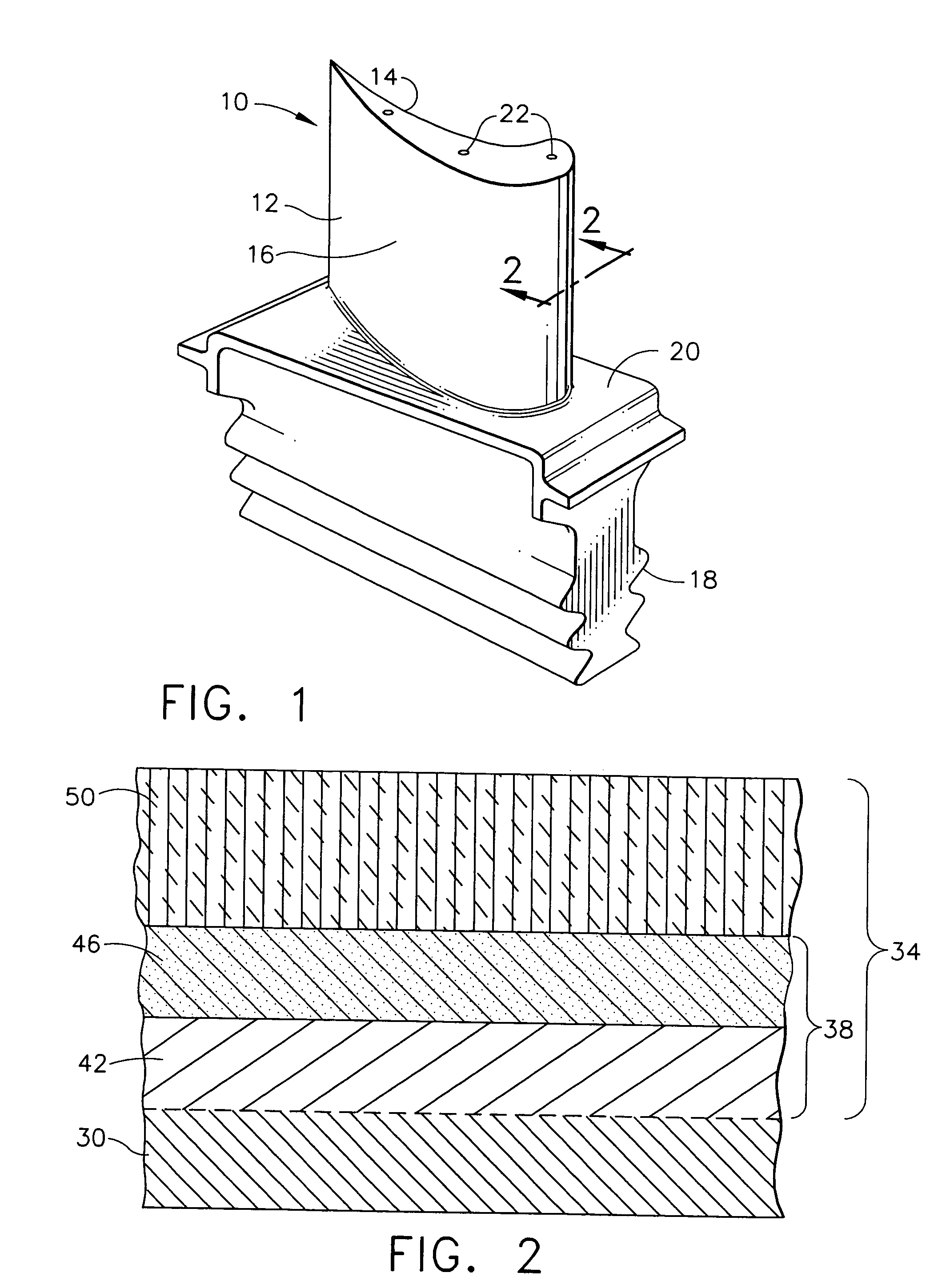
BACKGROUND OF THE INVENTION[0001]This invention relates to strengthened bond coats for thermal barrier coatings that protect metal substrates, and in particular to provide improved spallation resistance for such thermal barrier coatings. This invention further relates to articles, in particular turbine engine components, having a metal substrate that use such improved bond coats with such thermal barrier coatings.[0002]The operating environment within a gas turbine engine is both thermally and chemically hostile. Significant advances in high temperature alloys have been achieved through the formulation of iron, nickel and cobalt-base superalloys, though components formed from such alloys often cannot withstand long service exposures if located in certain sections of a gas turbine engine, such as the turbine, combustor and augmentor. A common solution is to provide turbine engine components with an environmental coating that inhibits oxidation and hot corrosion, or a thermal barrier ...

Claims


Application Information

Patent Timeline
Patent Type & Authority Patents(United States)
IPC IPC(8): C23C28/00F01D5/28
CPCC23C28/3215C23C28/34C23C28/341C23C28/345C23C28/36C23C28/3455Y10T428/12736Y10T428/12493Y10T428/12806Y10T428/265Y10T428/12875Y10T428/12576Y10T428/12618Y10T428/252Y10T428/12944Y10T428/25Y10T428/12535Y10T428/12611Y10T428/12937Y10T428/12931Y10T428/256
Inventor DAROLIA, RAMGOPALRIGNEY, JOSEPH DAVIDMARIJNISSEN, GILLION HERMANCAROLUS VERGELDT, ERIC RICHARD IRMAKLOOSTERMAN, ANNEJAN BERNARD
Owner GENERAL ELECTRIC CO
Learn More