Protection switching for duplex ATM-PON systems

a protection switching and atm-pon technology, applied in the field of passive optical networks, can solve the problems of not being able to have any signals in the second of the two networks, exhibiting equipment-related time-delay differences, and severely disturbing data traffi

Active Publication Date: 2005-11-29
WSOU INVESTMENTS LLC +1
View PDF6 Cites 7 Cited by
  • Summary
  • Abstract
  • Description
  • Claims
  • Application Information

AI Technical Summary

Benefits of technology

[0007]According to the principles of the invention, an arrangement and a method are provided for a protection switch in an ATM-PON system that can reliably switch between PONs in a hitless or near-hitless manner, e.g., with minimal loss of data and within a maximum protection switch tim

Problems solved by technology

Furthermore, ONTs may exhibit an equipment-related time-delay difference.
Disadvantageously, however, due to a switching delay, a protection switch will not be hitless in the aforementioned protection architectures (i.e. without loss of data), which may severely disturb data traffic.
In some protection architectures arranged with two separate networks, it is not possible to have any signals in the second of the two networks during operation of the first network due to the optical

Method used


Image

  • Protection switching for duplex ATM-PON systems
  • Protection switching for duplex ATM-PON systems
  • Protection switching for duplex ATM-PON systems

Examples


Embodiment Construction

[0021]The following list of acronyms and associated definitions will be used throughout the detailed description that follows:

[0022]

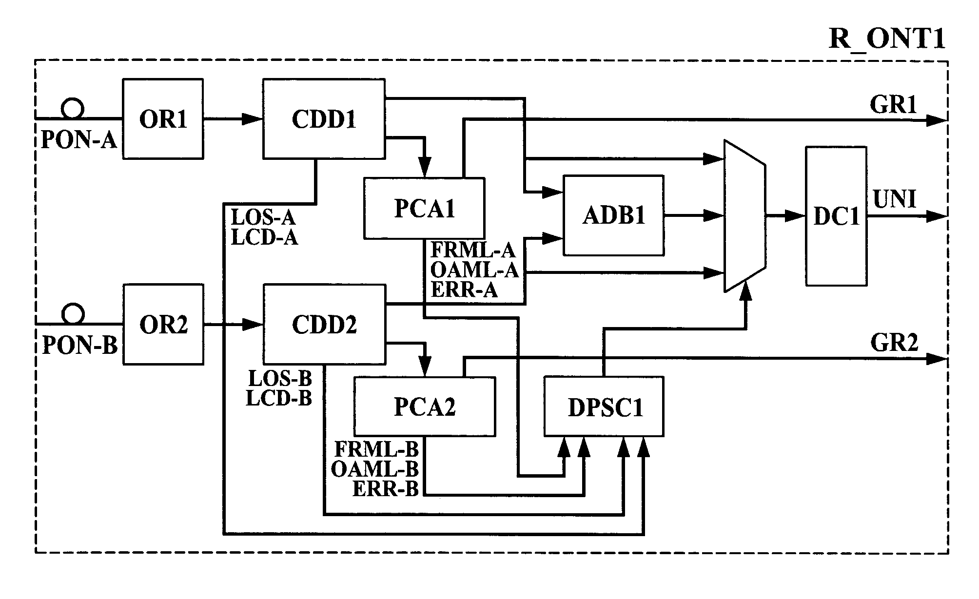
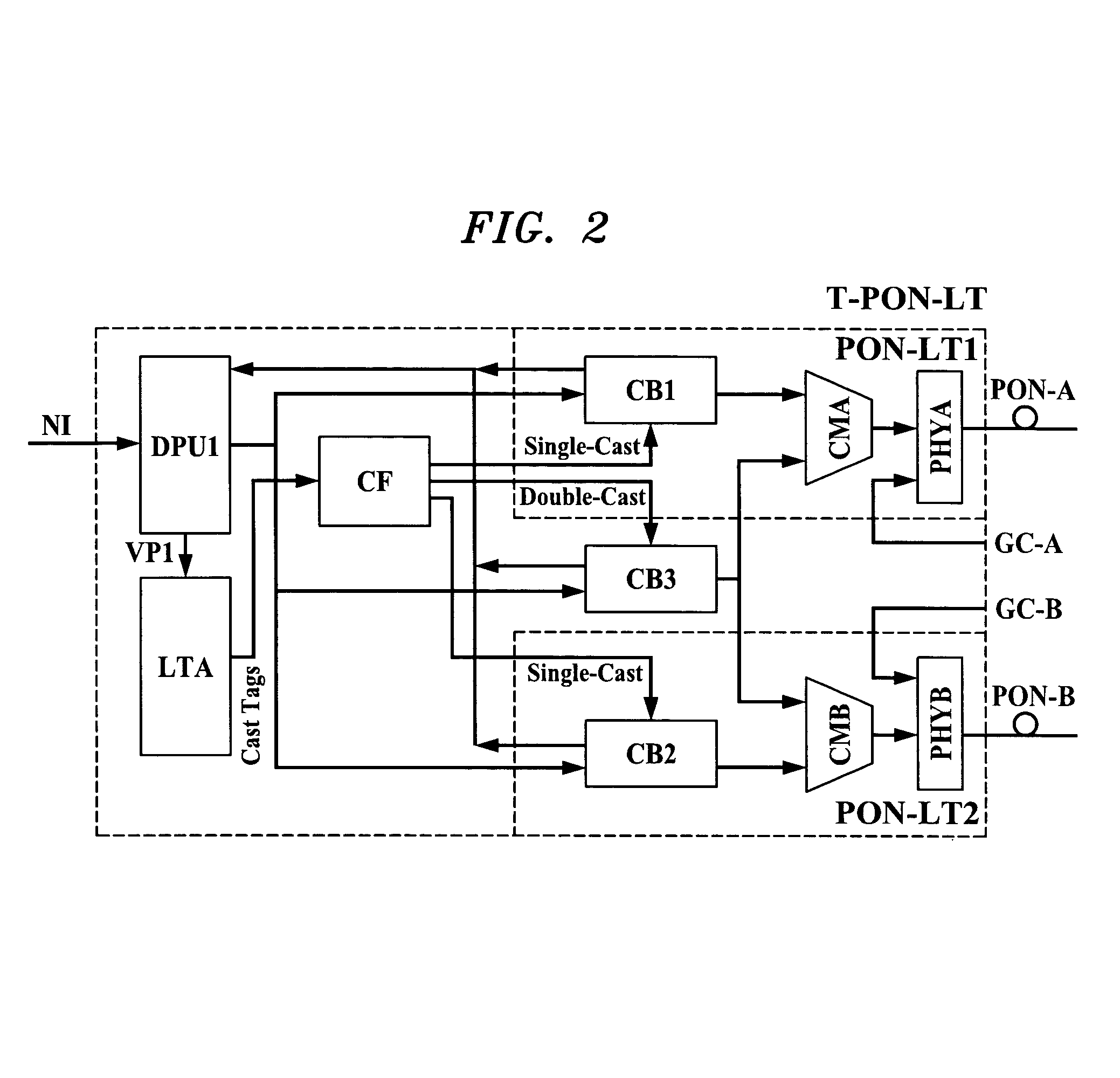
ADBadaptive data bufferATMasynchronous transfer modeCBcell buffer unitCDDcell delineation and descrambling unitCFcell filter unitCM(A / B)cell merger unitCQcell queueCRcell recovery unitDCdata conversion unitDPUdata packaging unitDPSCdownstream protection switch control unitERRerrorFIFOfirst in first out bufferFRMLloss of PLOAM frame synchronizationGC-(A / B)grant control code input (PON-A / PON-B)GDTIgrant delay time insertion unitGG(A / B)grant generatorGGPprotected grant generatorGISgrant insertion schedulerGRgrant signalILLAN interfaceIP(A / B)interface to physical layer unit (PHYA / PHYB)ISDNintegrated services data networkLANlocal area networkLCDloss of cell delineationLOSloss of signalLTAlookup table arrayMACmedium access controlMAGGmedium access control grant generatorNInetwork interfaceOAMLloss of Operations Administration and Maintenance dataOLToptical li...


PUM


Abstract

A terminal device is provided for communicating data signals with a central communication device via a first signal carrying line and a second signal carrying line. The first signal carrying line is arranged for transporting a first signal and the second signal carrying line is arranged for transporting a second signal, wherein the first and second signals have equal content. The first signal carrying line has a first propagation time and the second signal carrying line has a second propagation time, such that the first propagation time is shorter than the second propagation time. The terminal device includes a signal quality comparison element for determining a first signal quality of the first signal and a second signal quality of the second signal, for comparing the first and second signal qualities, and for accepting the one of the first and second signals that has a better quality.

Description

CROSS-REFERENCE TO RELATED APPLICATION[0001]This application claims priority of European Patent Application No. 00307188.3, filed on Aug. 21, 2000, which is incorporated herein by reference in its entirety.TECHNICAL FIELD[0002]The invention relates generally to passive optical networks (PONs) employing asynchronous transfer mode (ATM) transmission and, more particularly, to protection switching in such networks.BACKGROUND OF THE INVENTION[0003]Asynchronous Transfer Mode (ATM) systems provide communication services over high speed, high capacity networks. The communication services can comprise various protocols for data-communication, e.g. telephone services as public switched telephone network (PSTN) and integrated services data network (ISDN), digital video / audio broadcasting, Internet services, and so on. In one type of network configuration, an ATM switch capable of transmitting and receiving data may be connected to a range of subscribers to the communication services in a poin...

Claims


Application Information

Patent Timeline
IPC IPC(8): H04L12/44H04L12/70H04Q11/00H04Q11/04
CPCH04Q11/0066H04Q11/0478H04L2012/5605H04L2012/5627H04Q11/0067H04Q2011/0081
Inventor VAN HEYNINGEN, PIETER HENDRIKMAESSEN, JOHANNES H J
Owner WSOU INVESTMENTS LLC
Why Eureka
Try Eureka