Magnetic random access memory and method of writing data in magnetic random access memory
a random access memory and magnetic random access technology, applied in the direction of magnetic bodies, magnetic device details, magneticonductors/solid-state devices, etc., can solve the problems of increasing the write current and increasing the severity of the disturban
- Summary
- Abstract
- Description
- Claims
- Application Information
AI Technical Summary
Benefits of technology
Problems solved by technology
Method used
Image
Examples
first embodiment
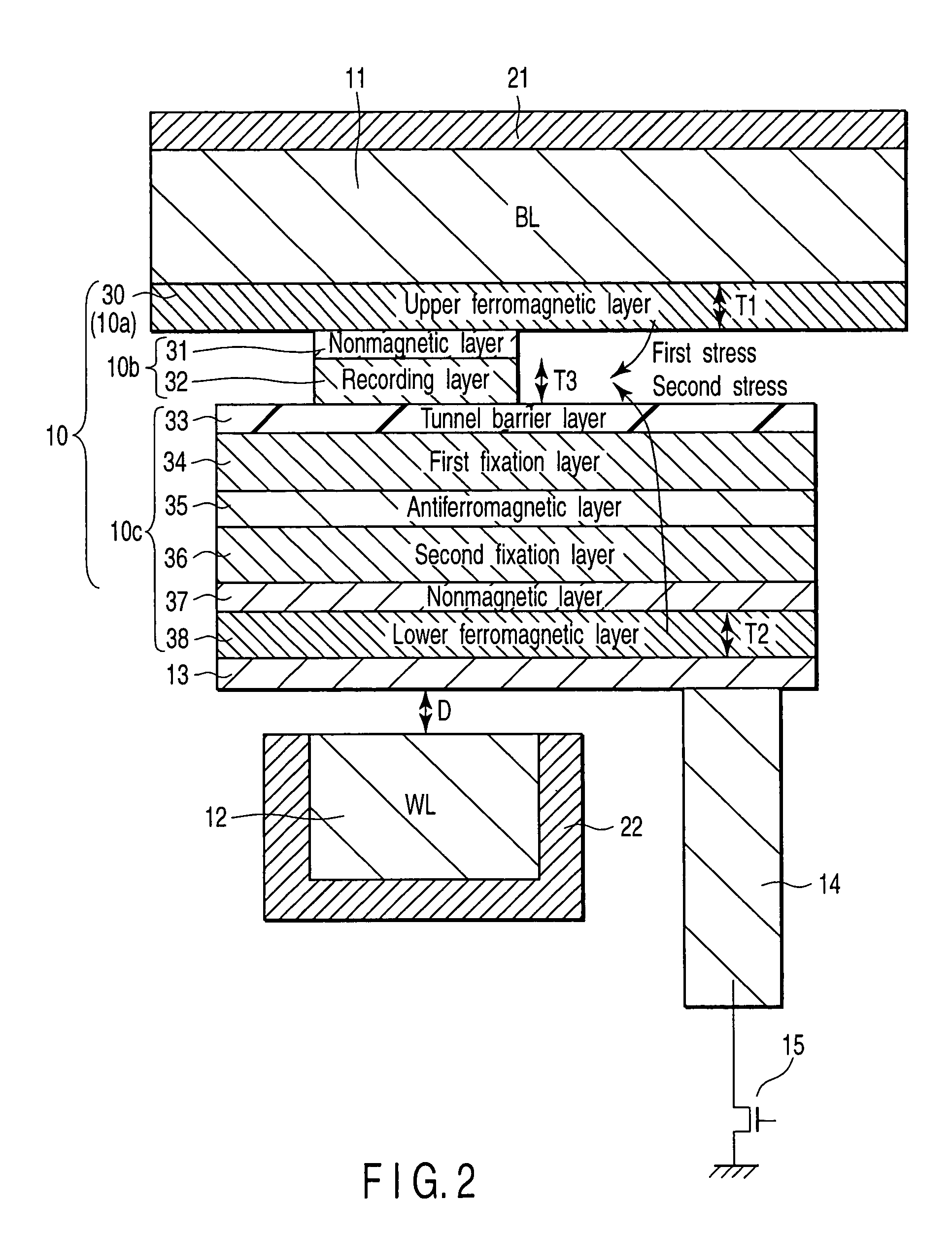
[0025]In a first embodiment, in an MTJ (Magnetic Tunnel Junction) element, ferromagnetic layers are provided over and under a recording layer, respectively, via nonmagnetic layers so that magnetostriction in the ferromagnetic layers can be transmitted to the recording layer. That is, toggle writes are carried out utilizing a magnetostriction interaction.
(1) Structure
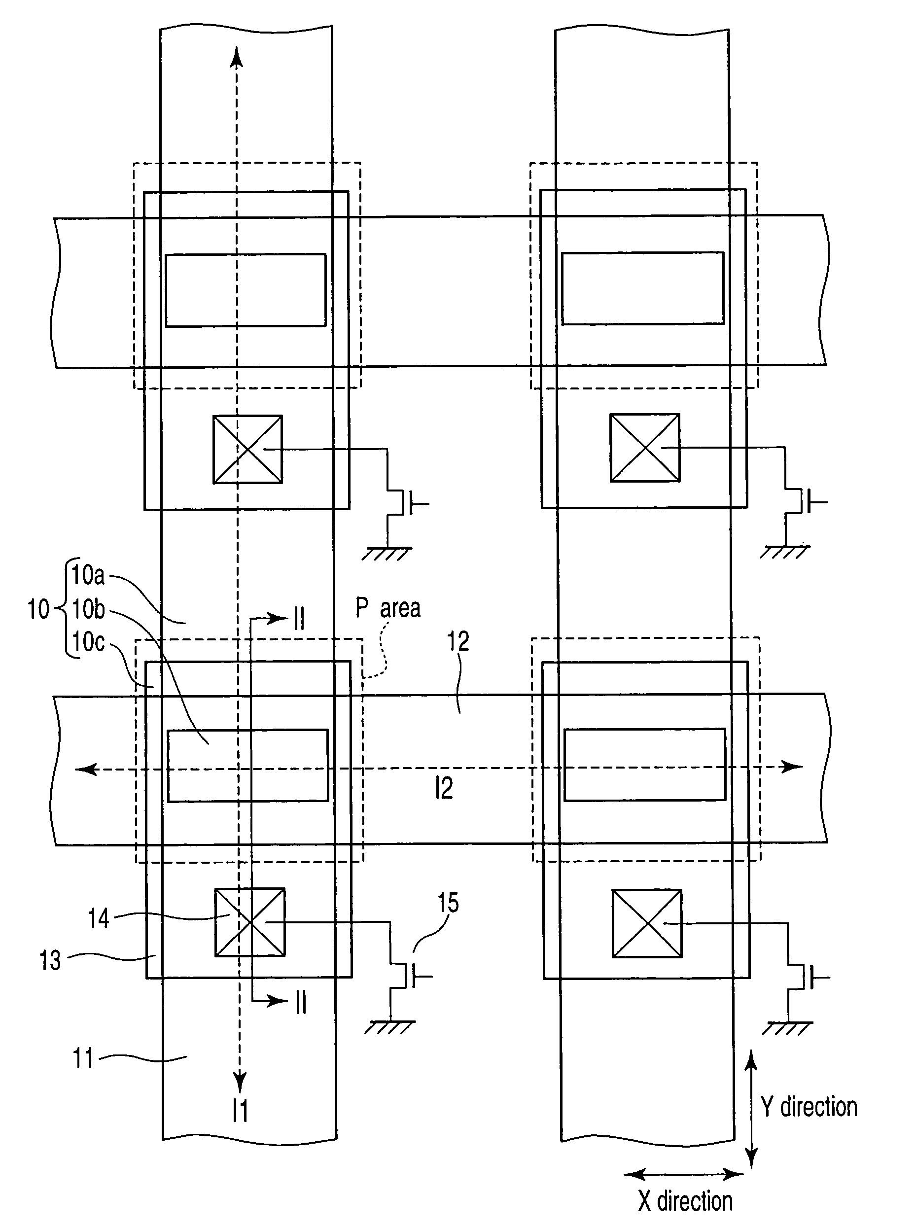
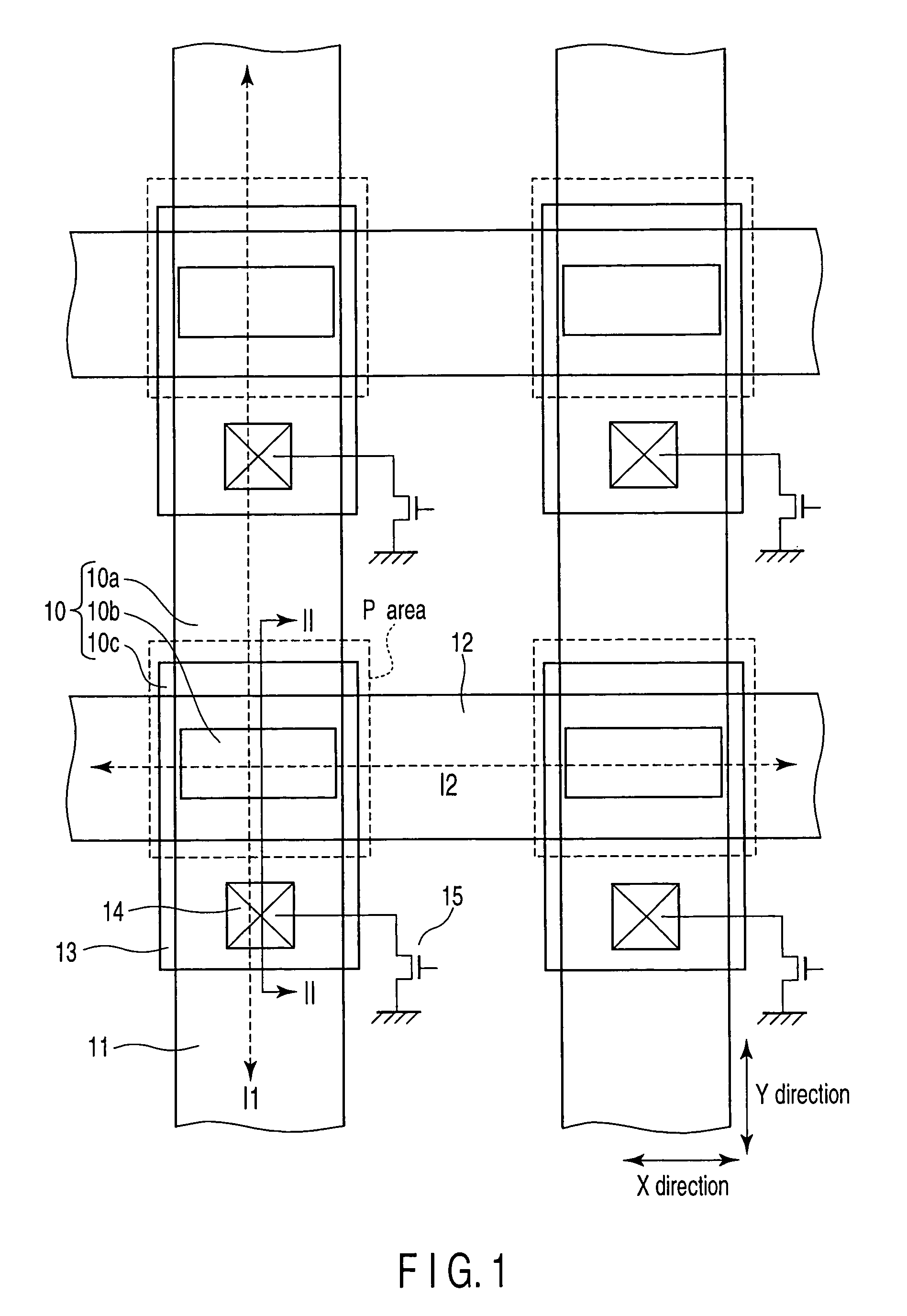
[0026]FIG. 1 is a schematic plan view showing a magnetic random access memory according to a first embodiment of the present invention. FIG. 2 is a sectional view of the magnetic random access memory taken along a line II—II in FIG. 1. FIG. 3 is a diagram showing the magnetization direction of each layer in the magnetic random access memory according to the first embodiment of the present invention. Description will be given of the structure of the magnetic random access memory according to the first embodiment.
[0027]As shown in FIGS. 1 and 2, a memory cell is shaped like a matrix in which bit lines (BL) 11 functioning a...
second embodiment
[0077]A second embodiment is obtained by deforming the structure of a third portion of the MTJ element according to the first embodiment.
[0078]FIG. 12 is a schematic sectional view of a magnetic random access memory according to a second embodiment of the present invention. Description will be given below of the structure of the magnetic random access memory according to the second embodiment.
[0079]As shown in FIG. 12, the second embodiment differs from the first embodiment in a third portion 10c of the MTJ element 10. The third portion 10c is composed of the tunnel barrier layer 33, the lower ferromagnetic layer 38, the nonmagnetic layer 37, the fixation layer 34, and the antiferromagnetic layer 35, which are arranged in this order in the vertical direction; the tunnel barrier layer 33 is located under the recording layer 32. Accordingly, the nonmagnetic layer 31 is provided between the recording layer 32 and the upper ferromagnetic layer 30. The nonmagnetic layer (tunnel barrier l...
third embodiment
[0084]In a third embodiment, gaps are formed around MTJ elements in order to relax the impact, on the MTJ elements, of the magnetostriction caused by an interlayer insulating film.
[0085]FIG. 13 is a schematic sectional view of a magnetic random access memory according to a third embodiment of the present invention. Description will be given below of the structure of the magnetic random access memory according to the third embodiment.
[0086]As shown in FIG. 13, the third embodiment differs from the first embodiment in that gaps 41 are formed in an interlayer insulating film 40 provided around the MTJ elements 10. The gaps 41 may be formed anywhere within the interlayer insulating film 40. However, the gaps 41 are desirably formed near the MTJ elements, notably their recording layers 32.
[0087]The third embodiment produces effects similar to those of the first embodiment. Moreover, according to the third embodiment, the gaps 41 are formed around the MTJ elements 10 in the interlayer ins...
PUM
| Property | Measurement | Unit |
|---|---|---|
| rotation | aaaaa | aaaaa |
| magneto-resistance | aaaaa | aaaaa |
| nonmagnetic | aaaaa | aaaaa |
Abstract
Description
Claims
Application Information
 - R&D
- Intellectual Property
- Life Sciences
- Materials
- Tech Scout
- Unparalleled Data Quality
- Higher Quality Content
- 60% Fewer Hallucinations
Browse by: Latest US Patents, China's latest patents, Technical Efficacy Thesaurus, Application Domain, Technology Topic, Popular Technical Reports.
© 2025 PatSnap. All rights reserved.Legal|Privacy policy|Modern Slavery Act Transparency Statement|Sitemap|About US| Contact US: help@patsnap.com


