
Electrolytic capacitor and its manufacturing method

a technology of electrolytic capacitors and manufacturing methods, applied in capacitors, electrolytes/absorbents, capacitor electrolytes, etc., can solve the problems of insufficient effect of lowering resistance, insufficient electric conductivity of separators made conductive by kneading or mixing carbon fibers or particles, and insufficient impedance enhancement of electrolyte, etc., to achieve excellent leak current characteristics, excellent reliability, and excellent impedance characteristics

Inactive Publication Date: 2005-11-08
PANASONIC CORP
View PDF19 Cites 35 Cited by
  • Summary
  • Abstract
  • Description
  • Claims
  • Application Information

AI Technical Summary

Benefits of technology

[0020]In this constitution, an electrolytic capacitor having an excellent impedance characteristic, an excellent leak current characteristic, an excellent reliability, and a high dielectric strength is obtained.

Problems solved by technology

In the conventional constitution, however, there was a limit in enhancement of conductivity of electrolyte, and its conductivity is at most about ten to scores of mS / cm at the present, and electrolyte having a sufficient conductivity is not developed yet, and an electrolytic capacitor of an electrolyte having a sufficient impedance characteristic is not obtained so far.
On the other hand, for decrease of resistance of separator, it has been attempted to decrease the separator thickness, lower the density, make uniform the pore size, or change from paper to high polymer nonwoven fabric, but due to lack of strength by lowering of density and other problems, a sufficient effect of lowering the resistance is not obtained yet.
Further, the separator made conductive by kneading or mixing carbon fibers or particles is not sufficient in the electric conductivity, and it was hard to obtain a separator of low density.
When using a separator by compounding graphite powder, there was a problem of increase of shorting due to drop of graphite powder and dispersion into electrolyte.
On the other hand, in the method of forming a conductive high polymer on the surface by chemical oxidation and polymerization from monomer of pyrrole, thiophen or aniline, it is difficult to compose an electrolytic capacitor of which rated voltage exceeds 35 V because there is almost no effect of deterioration of dielectric oxide film by oxidizing agent or chemical formation of conductive high polymer (defect repairing capability of dielectric oxide film).
If composed, however, increase of leak current or shorting between anode and cathode may occur during agent process or high temperature test.

Method used


Image

  • Electrolytic capacitor and its manufacturing method
  • Electrolytic capacitor and its manufacturing method
  • Electrolytic capacitor and its manufacturing method

Examples


embodiment 1

[0092](Embodiment 1)

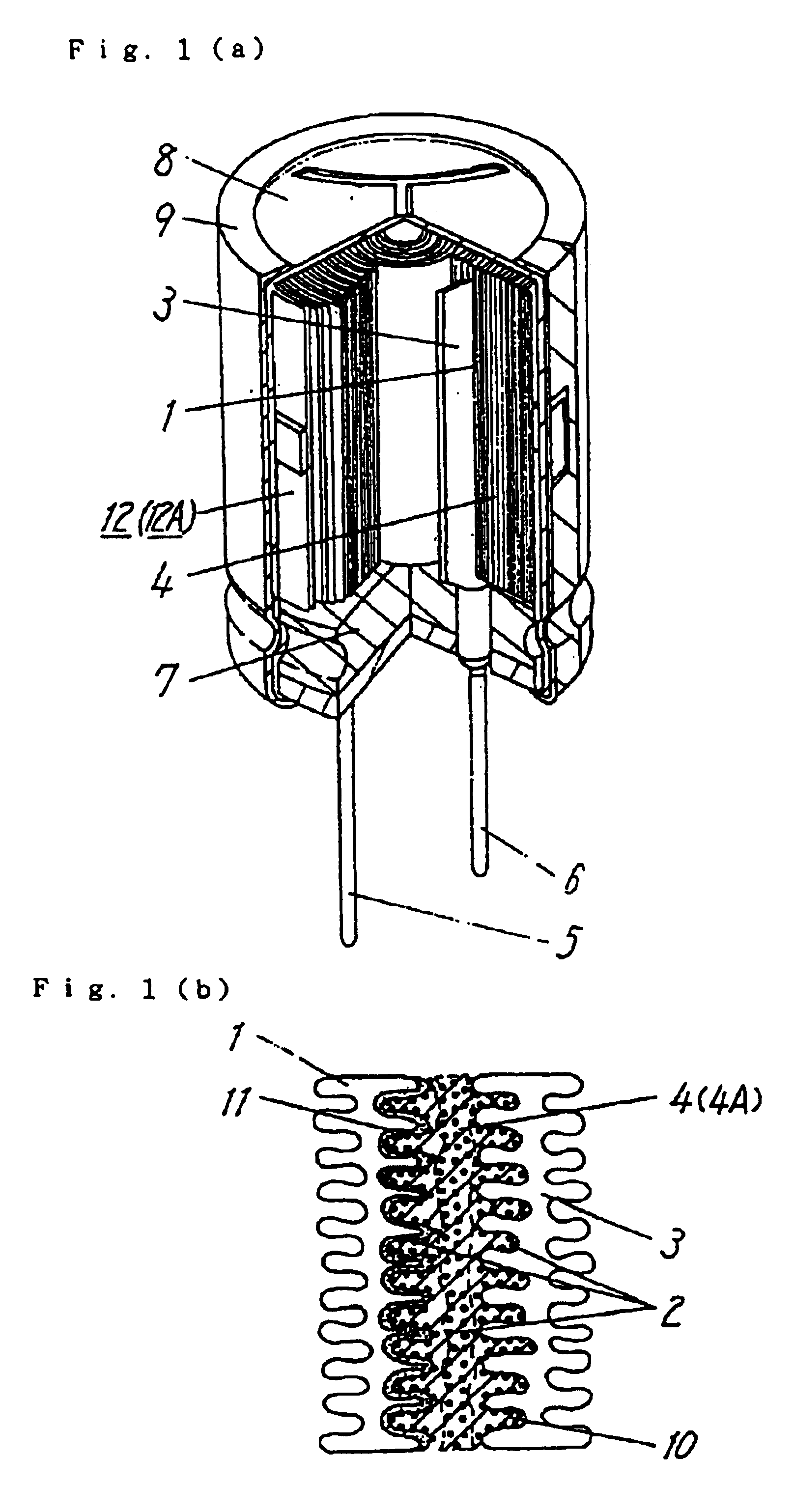
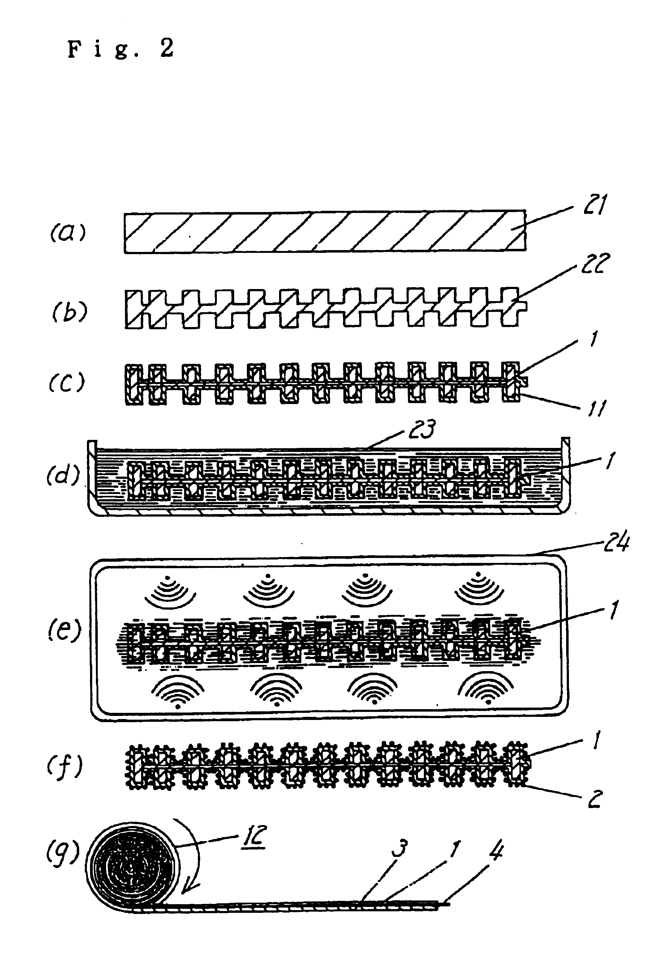
[0093]An anode aluminum foil and a cathode aluminum foil were wound around an electrolytic paper containing Manila hemp fibers (density 0.55 g / cm3, thickness 50 μm). Thus prepared winding type aluminum electrolytic capacitor was kept at temperature of 300° C. for 30 minutes, and the electrolytic paper was carbonized. Then, this capacitor element was immersed in a water-ethanol solution containing ethylene dioxythiophen and ferric sulfate, and lifted, and polymerized (10 minutes at 105° C.), and this process was repeated 10 times. The solid organic conductive material layer composed of polyethylene dioxythiophen thus polymerized chemically was formed on the electrode foils and between electrode foils. Consequently, the capacitor element was washed in water, and dried. Further, electrolyte A was impregnated in this capacitor element. As a result, an aluminum electrolytic capacitor element with rated voltage of 50 V and electrostatic capacity of 390 μF was obtained....

embodiment 2

[0094](Embodiment 2)

[0095]A glass fiber nonwoven cloth (density 0.13 g / cm3, thickness 50 μm), an anode aluminum foil, and a cathode aluminum foil were immersed in a water-ethanol solution containing pyrrole and ammonium persulfate, and lifted, dried and polymerized (10 minutes at 105° C.), and this process was repeated three times. Thus, a chemically polymerized polypyrrole was formed. Then, washing in water and drying, the separator made conductive by the chemically polymerized polypyrrole, and the anode aluminum foil and cathode aluminum foil having the chemically polymerized polypyrrole formed on the surface were obtained. Then, through this conductive separator, the anode aluminum foil and cathode aluminum foil having the chemically polymerized polypyrrole formed on the surface were wound, and a capacitor element was formed. It was further immersed in soluble sulfonated polyaniline solution at concentration of 10 wt. %, impregnated at reduced pressure, lifted, and dried. Thus, t...

embodiment 3

[0096](Embodiment 3)

[0097]On a glass fiber nonwoven cloth (density 0.13 g / cm3, thickness 50 μm), an anode aluminum foil, and a cathode aluminum foil, 7,7,8,8-tetracyanoquinodimethane complex in molten state was applied individually. Then, by cooling, the separator made conductive by the 7,7,8,8-tetracyanoquinodimethane complex, and the anode aluminum foil and cathode aluminum foil having the 7,7,8,8-tetracyanoquinodimethane complex formed on the surface were obtained. Then, through this conductive separator, the anode aluminum foil and cathode aluminum foil having the 7,7,8,8-tetracyanoquinodimethane complex formed on the surface were wound. Thus a capacitor element was formed. It was further immersed in soluble sulfonated polyaniline solution at concentration of 10 wt. %, impregnated at reduced pressure, lifted, and dried at a temperature below the melting point of the 7,7.8,8-tetracyanoquinodimethane complex. Thus, the residual dried sulfonated polyaniline was formed between the a...


PUM

PropertyMeasurementUnit
rated voltageaaaaaaaaaa
frequencyaaaaaaaaaa
temperatureaaaaaaaaaa

Abstract

A electrolytic capacitor includes(a) a capacitor element having a positive electrode, a negative electrode, and a solid organic conductive material disposed between the positive electrode and the negative electrode,(b) an electrolyte,(c) a case for accommodating the capacitor element and the electrolyte, and(d) a sealing member disposed to cover the opening of the case.The solid organic conductive material has at least one of organic semiconductor and conductive polymer. In this constitution, an electrolytic capacitor having excellent impedance characteristic, small current leak, excellent reliability, and high dielectric strength is obtained.

Description

[0001]This application is a division of Ser. No. 09 / 233,936 filed Jan. 20, 1999.FIELD OF THE INVENTION[0002]The present invention relates to an electrolytic capacitor as an electronic component, and its manufacturing method.BACKGROUND OF THE INVENTION[0003]In the recent trend of electronic appliances becoming digital and higher in frequency, the electrolytic capacitor, one of the electronic components, is required to be larger in capacity than in the conventional part and is superior in impedance characteristic in high frequency region. To meet such demand, it has been attempted to enhance the conductivity of the driving electrolyte (hereinafter called electrolyte), decrease the resistance of separator, or use a conductive compound obtained by making conductive a sheet insulator such as paper, cloth, nonwoven cloth or high polymer film, as a separator.[0004]Also as an attempt to make the separator conductive, various methods have been proposed, such as kneading or mixing of carbon f...

Claims


Application Information

Patent Timeline
Patent Type & Authority Patents(United States)
IPC IPC(8): H01G9/02H01G9/025H01G9/028H01G9/035H01G9/04
CPCH01G9/025H01G9/028Y10T29/417
Inventor SAITO, KAZUYONITTA, YUKIHIROTADA, HIROSHIIWAMOTO, SHIGEYOSHI
Owner PANASONIC CORP
Learn More