
Polymer electrolyte membrane fuel cells

a technology of electrolyte membrane and fuel cell, which is applied in the direction of fuel cell, fuel cell auxilary, electrochemical generator, etc., can solve the problems of significant loss of cell performance, reduced conductivity, and high pressure required to be of any practical use, and achieve high ionic conductivity, good performance, and high tolerance to fuel impurities

Inactive Publication Date: 2005-09-20
DANISH POWER SYST
View PDF14 Cites 85 Cited by
  • Summary
  • Abstract
  • Description
  • Claims
  • Application Information

AI Technical Summary

Benefits of technology

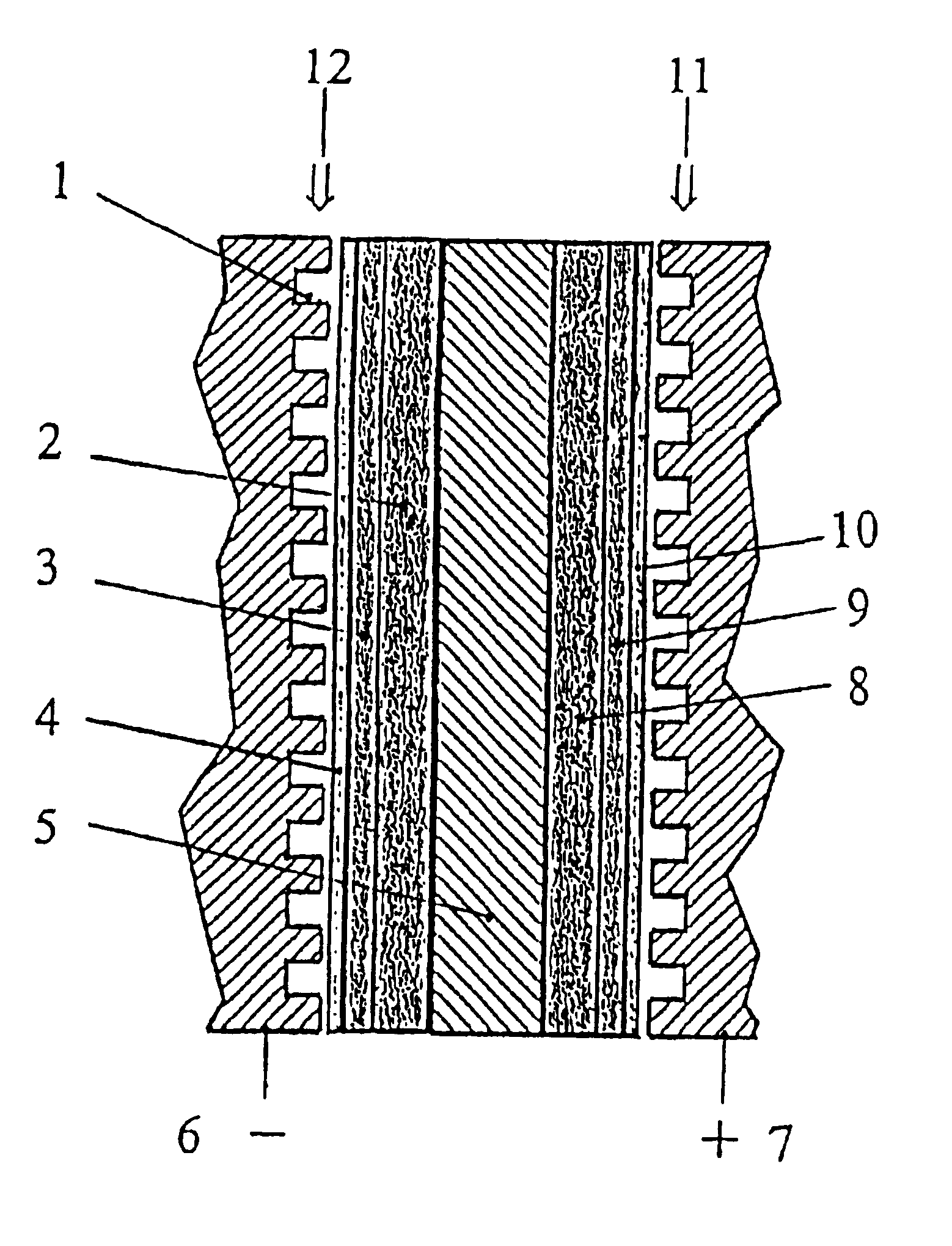
[0025]The assemblies prepared in this way give good performance and high tolerance to the fuel impurities e.g., carbon monoxide. Thus, the present invention also relates to the polymer electrolyte membranes (PEM) as such, to a fuel cell comprising a PEM and a method for operating the fuel cell.

Problems solved by technology

At higher temperatures, the conductivity is reduced dramatically since water is lost.
For an operation around 200° C., however, the pressure required will be too high to be of any practical use.
At 80° C., the typical operational temperature of a Nafion®-based polymer membrane electrolyte fuel cell, for example, the CO content as low as 20-50 ppm in the fuel steam will result in a significant loss in the cell performance.
For applications as a power system for automobiles, the direct usage of pure hydrogen eliminates the need to develop reliable on-board chemical processors; however, it faces other hurdles such as compact and light-weight fuel storage and network for fuel supply and distribution.
For a small dynamic load as in a vehicle, the main challenge for the on-board processing system is the complexity, which not only requires increased cost, size and volume, but also reduces the start-up time and transient response capacity of the system.
However the technology is far from satisfactory.
One of the major challenges is the anodic catalyst.
Although Pt / Ru alloy is still recognised as the best, it is not sufficiently active, resulting in high anodic overpotential loss (ca.
However, little effort has been made so far in this area, compared with other types of fuel cells such as phosphoric acid fuel cells or Nafion®-based polymer electrolyte membrane fuel cells.

Method used


Image

  • Polymer electrolyte membrane fuel cells
  • Polymer electrolyte membrane fuel cells
  • Polymer electrolyte membrane fuel cells

Examples


example 1

[0128]20 grams of 3 wt % PBI solution in dimethylacetamide were poured into a glass dish of 145 mm diameter. After drying in a ventilated oven at 85° C. for 30 hours, 100° C. for 10 hours, and then at 120° C. for 10 hours, the polymer membrane were washed with distilled water at 80° C. to remove the residual solvent and stabilising salts.

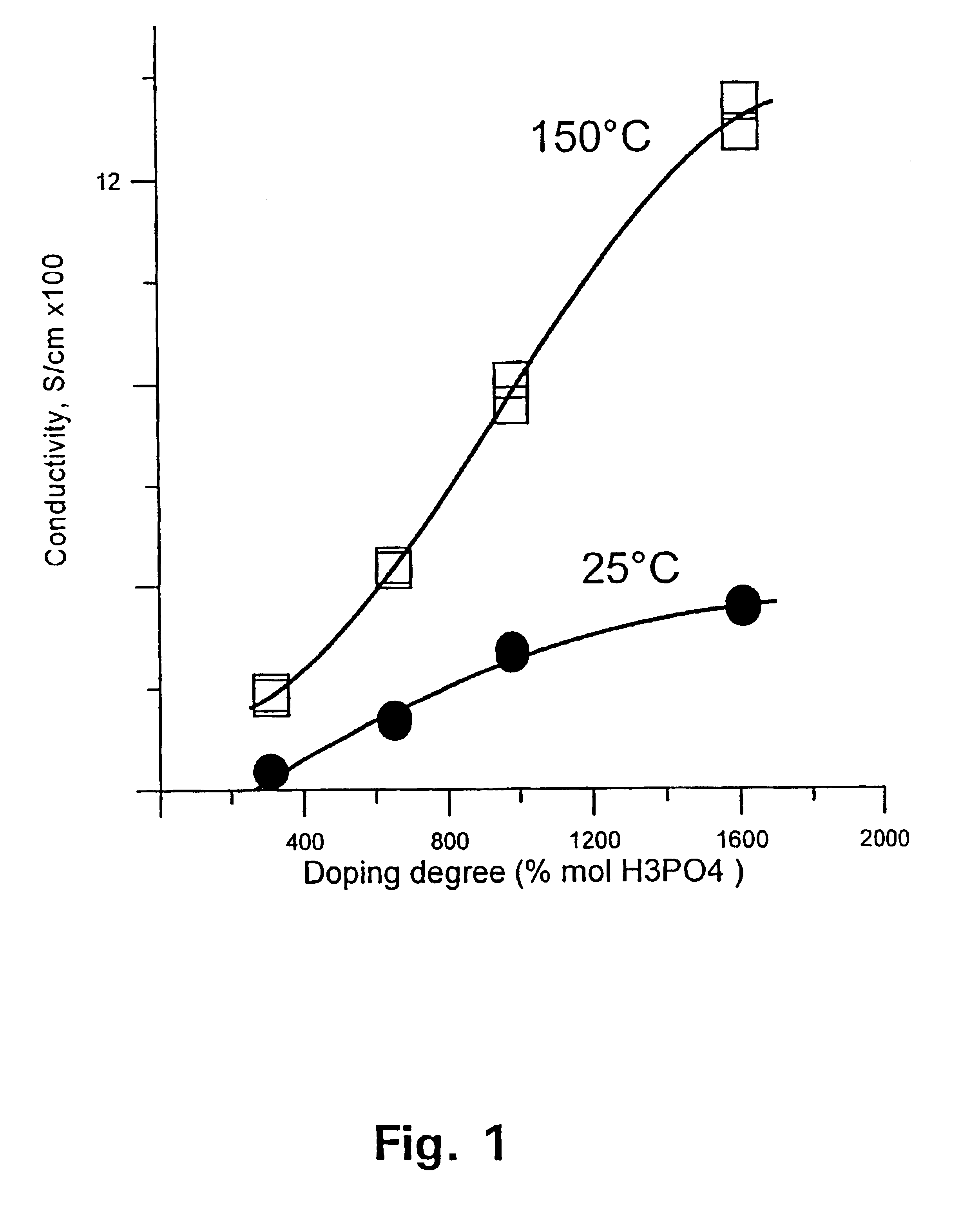
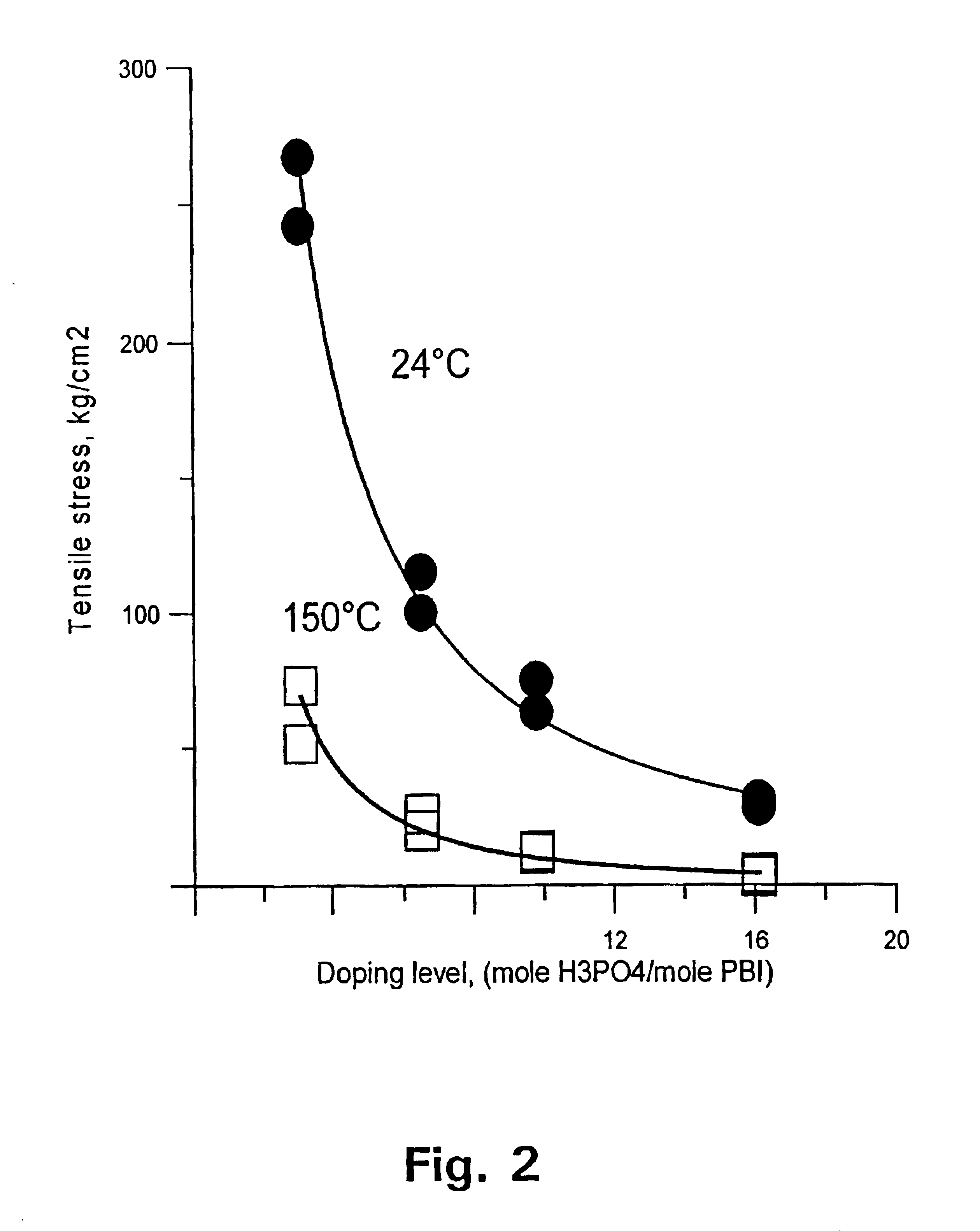
[0129]The membrane was thereafter immersed in phosphoric acid of concentration 50, 65, 75, and 90 wt %, respectively. After 15 days at room temperature, the membrane was doped at levels of 310, 650, 980, and 1610 mol %, accordingly. FIG. 1 shows the conductivity of the membrane as a function of the doping level at temperatures of 25 and 150° C., respectively. FIG. 2 shows the tensile stress of the membrane as a function of the doping level at temperatures of 25 and 150° C., respectively.

example 2

[0130]Onto a wet-proofed carbon backing substrate (Toray paper TGP-H-120, Toray Ind. Inc.) a slurry of 60 wt % carbon powder (Vulcan XC-72, Cabot) and 40 wt % polytetrafluoro-ethylene (PTFE) was applied. The resulting layer was then dried and sintered at 370° C. for 20 minutes. This supporting layer is hydrophobic so that it allows access of reactive gases. As a bridge between the carbon paper backing and the catalyst layer this layer prevents also the electrode from serious cracking after drying and sintering.

[0131]A mixture of 40 wt % Pt / C catalyst powder and 60 wt % PBI from a 3 wt % polymer solution in dimethylacetamide was well mixed and applied on to the supporting layer of the carbon paper by tape-casting. The platinum loading in the catalyst layer is 0.45 mg / cm2. After drying at 130° C. for 10 minutes, the electrode was impregnated with a mixed acid of 65 wt % phosphoric acid and 35 wt % trifluoroacetic acid. The amount of impregnated phosphoric acid is related to the PBI co...

example 3

[0133]On to the wet-proofed carbon substrate (Toray paper TGP-H-120, Toray Ind. Inc.) a slurry of 60 wt % carbon powder (Vulcan XC-72, Cabot) and 40 wt % PTFE was applied and then dried and sintered at 370° C. for 20 minutes.

[0134]A mixture of 45 wt % PVC catalyst powder and 55 wt % PBI from a 2 wt % solution in dimethylacetamide was prepared and applied on to the supporting layer of the carbon substrate, as the cathode. A mixture of 45 wt % Pt—Ru / C catalyst powder and 55 wt % PBI from a 2 wt % solution in dimethylacetamide was prepared and applied on to the supporting layer of the carbon substrate, as the anode. The platinum loading in the catalyst layer of both electrodes was 0.45 mg / cm2. After drying at 130° C. for 5 minutes, the electrode was impregnated with a mixed acid of 60 wt % phosphoric acid and 40 wt % trifluoroacetic acid. The amount of impregnated phosphoric acid was related to the PBI content in the catalyst layer of the electrode, being in a molar ratio of 12 to 1.

[0...


PUM

PropertyMeasurementUnit
molar ratioaaaaaaaaaa
temperatureaaaaaaaaaa

Abstract

A method for preparing polybenzimidazole or polybenzimidazole blend membranes and fabricating gas diffusion electrodes and membrane-electrode assemblies is provided for a high temperature polymer electrolyte membrane fuel cell. Blend polymer electrolyte membranes based on PBI and various thermoplastc polymers for high temperature polymer electrolyte fuel cells have also been developed. Miscible blends are used for solution casting of polymer membranes (solid electrolytes). High conductivity and enhanced mechanical strength were obtained for the blend polymer solid electrolytes. With the thermally resistant polymer, e.g., polybenzimidazole or a mixture of polybenzimidazole and other thermoplastics as binder, the carbon-supported noble metal catalyst is tape-cast onto a hydrophobic supporting substrate. When doped with an acid mixture, electrodes are assembled with an acid doped solid electrolyte membrane by hot-press. The fuel cell can operate at temperatures up to at least 200° C. with hydrogen-rich fuel containing high ratios of carbon monoxide such as 3 vol % carbon monoxide or more, compared to the carbon monoxide tolerance of 10-20 ppm level for Nafion®-based polymer electrolyte fuel cells.

Description

[0001]This application is the national phase under 35 U.S.C. §371 of PCT International Application No. PCT / DK00 / 00495 which has an International filing date of Sep. 8, 2000, which designated the United States of America.FIELD OF THE INVENTION[0002]The present invention is directed to the field of polymer electrolyte membrane fuel cells, in particular to the preparation of gas diffusion electrodes and membrane-electrode assemblies for high temperature polymer electrolyte membrane fuel cells. The fuel cell according to the invention can operate at temperatures of up to at least 200° C. even with hydrogen fuel containing a relatively high amount of carbon monoxide, i.e. even 3 vol % carbon monoxide or more. The present invention also provides superior polymer electrolyte membranes based on blends of polybenzimidazole and thermoplastic polymers.BACKGROUND OF THE INVENTION[0003]In operation of a polymer electrolyte fuel cell, an oxygen-containing gas is fed to the cathode and a fuel-cont...

Claims


Application Information

Patent Timeline
Patent Type & Authority Patents(United States)
IPC IPC(8): H01M4/88H01M4/90H01M4/92H01M8/10H01M4/86
CPCH01M4/8605H01M4/8807H01M4/8828H01M4/92H01M4/926H01M8/1004H01M8/1023H01M8/1027H01M8/103H01M8/1032H01M8/1044H01M8/1048H01M4/8668Y10T29/49108H01M2300/0082Y02E60/521Y10T29/49115Y02E60/50
Inventor BJERRUM, NIELS JANNIKSENLI, QINGFENGHJULER, HANS AAGE
Owner DANISH POWER SYST
Learn More