
Self-regulating hydrogen generator

a hydrogen generator and self-regulating technology, applied in the direction of liquid chemical processes, physical/chemical process catalysts, lighting and heating apparatus, etc., can solve the problems of reducing affecting the hydrogen generation process, and affecting so as to increase or decrease the hydrogen generation rate

Inactive Publication Date: 2005-09-06
PROTONEX TECH CORP
View PDF13 Cites 116 Cited by
  • Summary
  • Abstract
  • Description
  • Claims
  • Application Information

AI Technical Summary

Benefits of technology

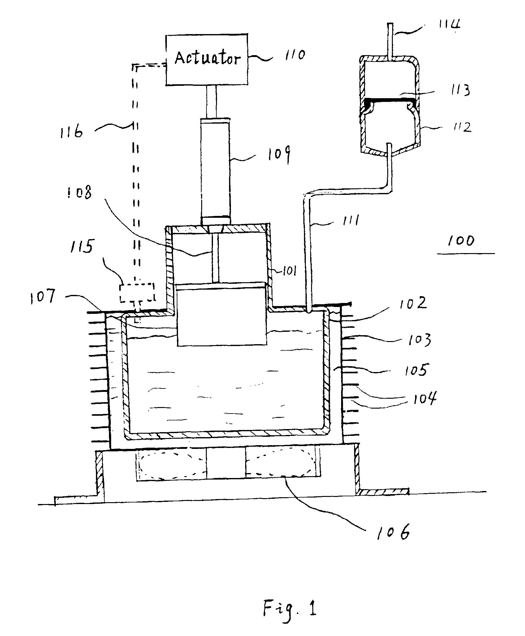
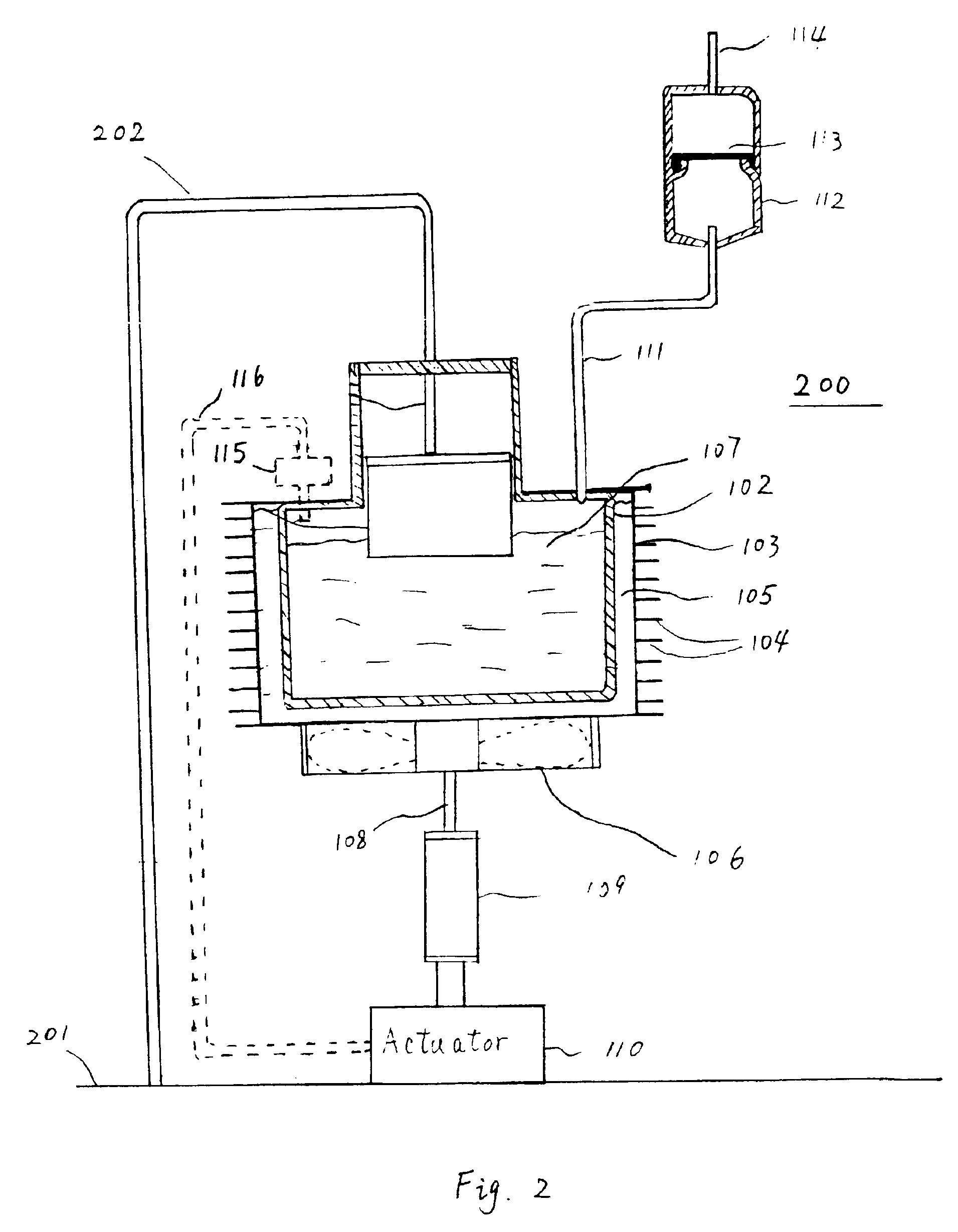
[0005]Broadly, pursuant to the present invention, a self-regulating hydrogen generating system is provided. More specifically, the hydrogen generation system in accordance with the present invention regulates the rate of hydrogen generation by providing relative movement between the fuel tank and the catalyst chamber so as to increase or decrease the hydrogen generation rate. This relative movement provided is in response to the monitoring of one or more parameters of the hydrogen generation process.
[0006]In the disclosed embodiments, the catalyst chamber is disposed in a tank containing the fuel. The relative movement provided moves the catalyst chamber toward the fuel solution so as to increase the rate of hydrogen generation and moves the catalyst chamber away from the fuel solution to decrease such generation. Advantageously, such self-regulation can be provided without an external power source in a compact fashion and can be varied to meet the requirements of different commercial applications. The overall system may use a single tank for the fuel and spent fuel solution, is compact and can be fabricated using commercially available parts.

Problems solved by technology

In addition, the rate of decomposition of the complex metal hydride into hydrogen gas and a metal metaborate is pH dependent, with higher pH values hindering the hydrolysis.
While these systems perform satisfactorily in many applications, they are larger than is desired for other applications and, in addition, require a source of power for the fuel pump.
In this system, the catalyst bed is fixed in place and the pressure produced by generated hydrogen causes the solution to be forced away from the catalyst, thereby slowing down the hydrogen generation process.

Method used


Image

  • Self-regulating hydrogen generator
  • Self-regulating hydrogen generator
  • Self-regulating hydrogen generator

Examples


Embodiment Construction

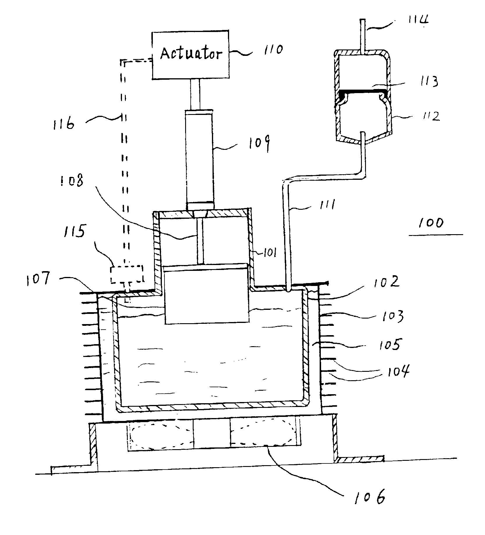
[0011]Refer now to FIG. 1 which shows a portable, compact, self-regulating hydrogen generation system in accordance with the preferred embodiment of the present invention. System 100 includes a single fuel tank 101 for holding a fuel solution capable of generating hydrogen. This solution, for certain applications, also contains a stabilizer, such as sodium hydroxide. As the generation of hydrogen is an exothermic reaction, tank 101 is preferably a double-walled tank having inner wall 102 and outer wall 103 for those applications where a high rate of hydrogen generation is required. The space between walls 102 and 103 may be filled with material 105 having a high specific heat, e.g., water, which serves as a heat sink for the system. Such heat transfer is further enhanced by incorporating a plurality of fins in the tank's walls. The fins may be disposed in either one or both of the wall surfaces and may be in either one or both of the inner wall 102 and outer wall 103. As shown in FI...


PUM

PropertyMeasurementUnit
Volumeaaaaaaaaaa
Volumeaaaaaaaaaa
Shapeaaaaaaaaaa

Abstract

A hydrogen generating system regulates its rate of hydrogen generation by monitoring one or more parameters of the hydrogen generation process and then providing relative movement between the fuel tank and the catalyst chamber so as to increase or decrease the rate of hydrogen generation.In the disclosed embodiments, the catalyst chamber is disposed in a tank containing the fuel. The relative movement provided moves the catalyst chamber toward the fuel solution so as to increase the rate of hydrogen generation and moves the catalyst chamber away from the fuel solution to decrease such generation. Advantageously, such self-regulation can be provided without an external power source and can be varied to meet the requirements of different commercial applications. The overall system can be readily fabricated using commercially available parts.

Description

TECHNICAL FIELD[0001]The present invention relates to a hydrogen generating system and, more particularly, to such a system that is self-regulating and does not require any external power source to operate.BACKGROUND OF THE INVENTION[0002]The hydrolysis reactions of many complex metal hydrides, including sodium borohydride (NaBH4), have been commonly used for the generation of hydrogen gas. The governing chemical reaction for such hydrolysis may be expressed as: where MBH4 and MBO2 respectively represent a metal borohydride and a metal metaborate. As the hydrolysis of sodium borohydride is typically slow at room temperature, heat or a catalyst, e.g., acids or a variety of transition metals, can be used to accelerate the hydrolysis reaction. The transition metals can include ruthenium, cobalt, nickel, or iron, or corresponding metal salts in solution or as solids, or metal borides as suspensions, or such salts, borides or metals can be deposited on inert supports. In addition, the ra...

Claims


Application Information

Patent Timeline
IPC IPC(8): C01B3/00C01B3/06B01J7/02B01J8/08B01J16/00
CPCB01J7/02B01J8/082B01J16/005C01B3/065B01J2208/00548Y02E60/362Y02E60/36
Inventor STRIZKI, MICHAELSHAH, SHAILESH
Owner PROTONEX TECH CORP
Learn More